
Large crawler type integrated horizontal directional drilling rig

A horizontal directional drilling rig and crawler type technology, applied in the field of large-scale crawler-type integrated horizontal directional drilling rig and trenchless equipment, can solve the problems of integrated installation, can only be separated separately, increased cost, inconvenient transportation, etc., to reduce hydraulic oil pipelines The effect of connecting, preventing hydraulic oil leakage, and reducing production costs

Pending Publication Date: 2020-08-07
江苏谷登重型机械装备科技有限公司
View PDF0 Cites 1 Cited by
  • Summary
  • Abstract
  • Description
  • Claims
  • Application Information

AI Technical Summary

Problems solved by technology

[0002] For large crawler-type horizontal directional drilling rigs, it is difficult to integrate the main engine and the main power system due to the limitation of transportation size and weight. The usual method is to separate the main engine and the main power system, and connect them with hydraulic oil pipelines during work. It is transported separately from the main power system, which leads to a series of problems such as the increase of the total cost of the customer, the inconvenience of transportation, the increase of transportation costs, the increase of energy consumption, and the increase of pollution sources
[0003] Specifically, take the traditional 500-ton level horizontal directional drilling rig as an example, which has the following disadvantages: 1. The main engine and the power system are large in size and occupy a large space. Combined together; 2. The main engine needs an auxiliary walking power station to move, load and unload, which increases production costs and energy consumption, and is connected to the power system through hydraulic oil pipelines, which increases pollution sources. Cost; 3. There are more auxiliary walking power stations and hydraulic oil pipelines, the cost has increased significantly, and the cost of each unit has increased by about 200,000 yuan

Method used


Image

  • Large crawler type integrated horizontal directional drilling rig
  • Large crawler type integrated horizontal directional drilling rig
  • Large crawler type integrated horizontal directional drilling rig

Examples


Embodiment Construction

[0026] In order to further illustrate the technical solutions adopted by the present invention and the technical effects achieved, the following will be described in detail in conjunction with the embodiments and accompanying drawings.

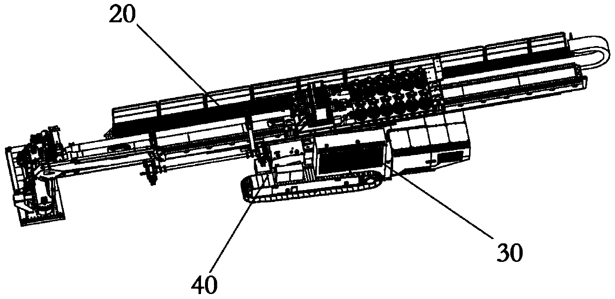
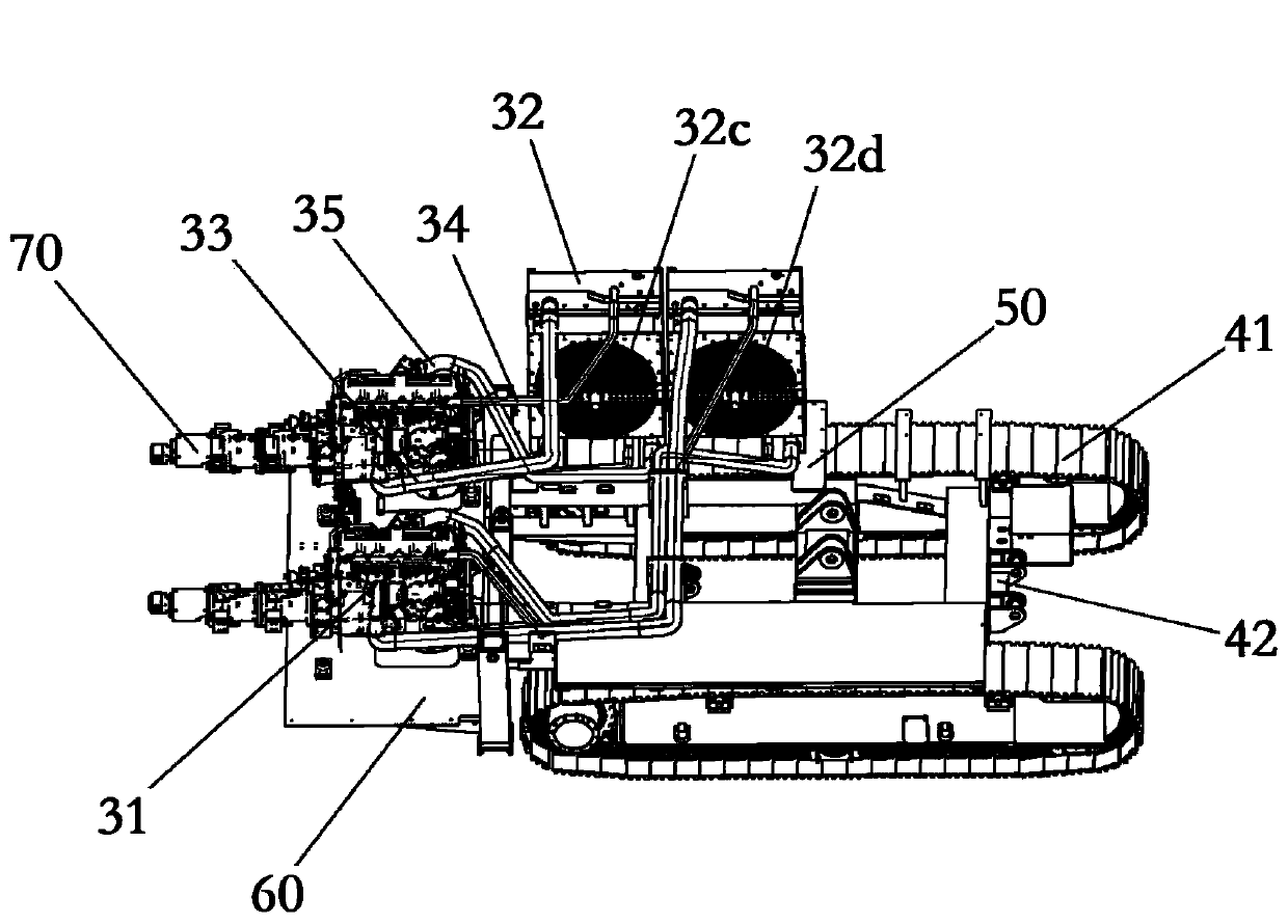
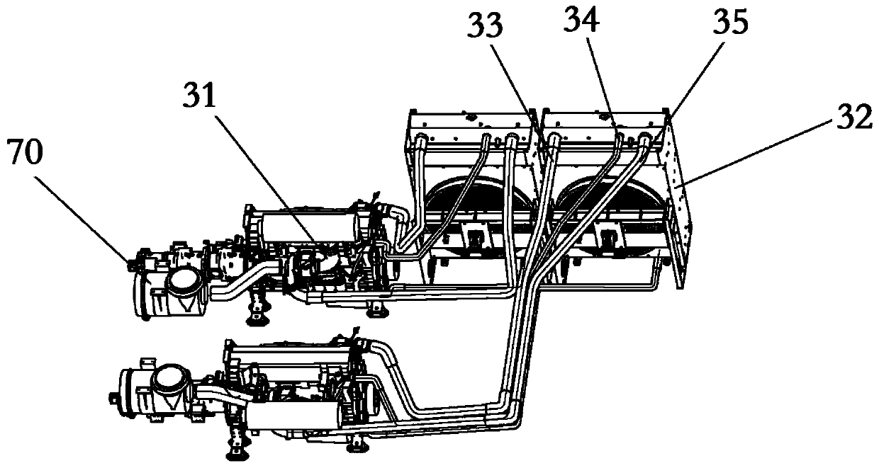
[0027] refer to Figure 1 to Figure 3 , the present invention provides a large crawler-type integrated horizontal directional drilling machine, which includes a main machine part 20 , a power part 30 , a running part 40 , a first connecting frame 50 and a second connecting frame 60 . The main unit 20 includes the main body of the drilling rig, the power unit 30 includes two engines 31 and two cooling water tanks 32, the running unit 40 includes symmetrically arranged track wheels 41 and a track beam frame 42 connected to the track wheels 41, and the main unit 20 is fixed on the track beam Rack 42. Both the first connecting frame 50 and the second connecting frame 60 are connected and fixed to the track beam frame 42, the first connecting fram...


PUM


Abstract

The purpose of the invention is to provide a large crawler type integrated horizontal directional drilling rig. The large crawler type integrated horizontal directional drilling rig includes a main machine part, a power part, a walking part, a first connecting frame and a second connecting frame; wherein the first connecting frame is arranged above a crawler wheel, the second connecting frame is arranged on the end of the crawler wheel, an engine is arranged on the second connecting frame, and a heat dissipation water tank is arranged on the first connecting frame or the second connecting frame. The large crawler type integrated horizontal directional drilling rig has the advantages of saving space, convenient transportation, reducing pollution, lowering cost and the like.

Description

technical field [0001] The invention relates to a non-excavation equipment in the field of construction machinery, in particular to a large crawler-type integrated horizontal directional drilling machine. Background technique [0002] For large crawler-type horizontal directional drilling rigs, it is difficult to integrate the main engine and the main power system due to the limitation of transportation size and weight. The usual method is to separate the main engine and the main power system, and connect them with hydraulic oil pipelines during work. It is transported separately from the main power system, which leads to a series of problems such as the increase of the total cost of the customer, the inconvenience of transportation, the increase of transportation costs, the increase of energy consumption, and the increase of pollution sources. [0003] Specifically, take the traditional 500-ton level horizontal directional drilling rig as an example, which has the following...

Claims


Application Information

Patent Timeline
IPC IPC(8): E21B7/02E21B7/04F01P11/00F01P11/04
CPCE21B7/02E21B7/04F01P11/00F01P11/04
Inventor 陈凤钢赵俊锋胡孝新李彬程熙石姚姚
Owner 江苏谷登重型机械装备科技有限公司
Learn More