Hydraulic heat dissipation controlling system, method, device and equipment and engineering machine

A control system and hydraulic technology, applied in the direction of fluid pressure actuation device, fluid pressure actuation system components, mechanical equipment, etc., can solve the problems of time-consuming and oil-consuming, low heat dissipation efficiency of hydraulic system, affecting the working efficiency of construction machinery, etc. Improve heat dissipation efficiency and ensure the effect of working efficiency

Inactive Publication Date: 2020-08-11
SHANGHAI SANY HEAVY IND
View PDF9 Cites 0 Cited by
  • Summary
  • Abstract
  • Description
  • Claims
  • Application Information

AI Technical Summary

Problems solved by technology

[0004] However, the use of the existing technology is time-consuming and fuel-intensive, resulting in low heat dissipation efficiency of the hydraulic system control and affecting the working efficiency of construction machinery.

Method used


Image

  • Hydraulic heat dissipation controlling system, method, device and equipment and engineering machine
  • Hydraulic heat dissipation controlling system, method, device and equipment and engineering machine
  • Hydraulic heat dissipation controlling system, method, device and equipment and engineering machine

Examples


Embodiment Construction

[0046] In order to make the purpose, technical solutions and advantages of the embodiments of the present invention clearer, the technical solutions in the embodiments of the present invention will be clearly and completely described below in conjunction with the drawings in the embodiments of the present invention. Obviously, the described embodiments It is a part of embodiments of the present invention, but not all embodiments.

[0047] Construction machinery is a machine that integrates heat source and heat dissipation source. If its heat balance exceeds or fails to reach the heat balance temperature range (ie, overheating or undercooling), it will have an adverse effect on the reliability, environmental protection and efficiency of construction machinery operation.

[0048] For example, the optimal heat balance parameters of construction machinery are as follows: diesel engine water temperature 75°C-95°C, hydraulic oil temperature 55°C-75°C, torque converter oil temperature...


PUM


Abstract

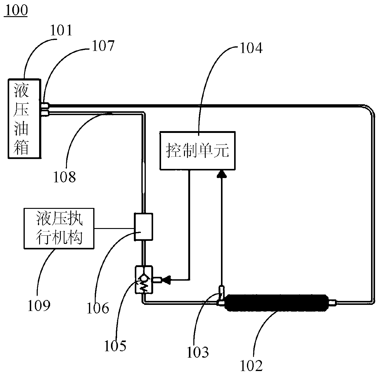
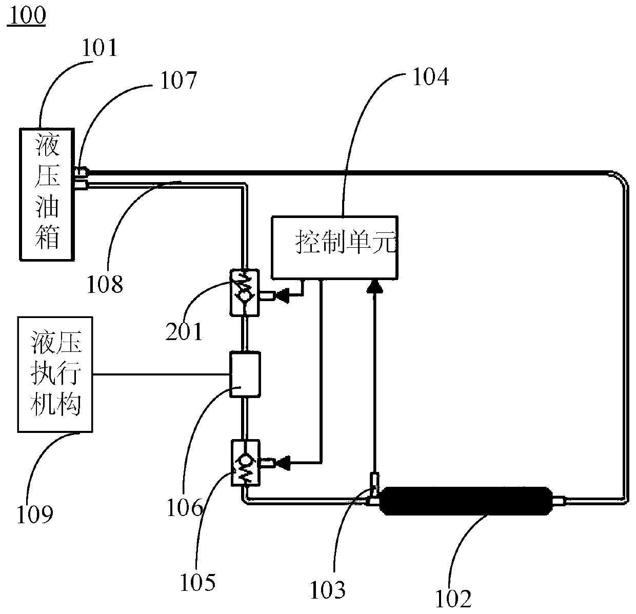
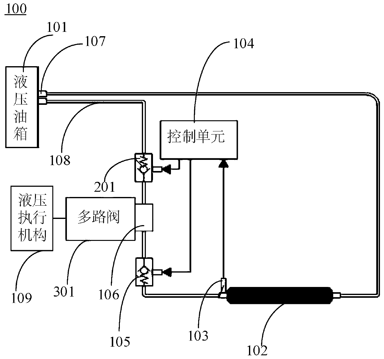
The invention provides a hydraulic heat dissipation controlling system, method, device and equipment and an engineering machine and relates to the technical field of engineering machines. The hydraulic heat dissipation controlling system comprises a hydraulic oil tank, a hydraulic oil radiator, a pressure sensor, a control unit, a first back pressure valve and an oil return block. The oil inlet end of the hydraulic oil radiator is provided with the pressure sensor, and the oil inlet end communicates with one end of the first back pressure valve. The other end of the first back pressure valve communicates with the first end of the oil return block. The second end of the oil return block communicates with a second oil return port of the hydraulic oil tank, and the third end of the oil returnblock communicates with the return oil output end of at least one hydraulic actuating mechanism. The pressure sensor is in communication connection with the control unit, and transmits the collectedpressure value of the oil inlet end of the hydraulic oil radiator to the control unit. The control unit is in communication connection with the first back pressure valve, and adjusts the first back pressure valve according to the pressure value. According to the hydraulic heat dissipation controlling system, method, device and equipment and the engineering machine, the pressure at the inlet end ofthe hydraulic oil radiator can be controlled, so that the heat dissipation efficiency of the hydraulic heat dissipation control system is improved, and the working efficiency of the engineering machinery is improved.

Description

technical field [0001] The invention relates to the technical field of construction machinery, in particular to a hydraulic heat dissipation control system, method, device, equipment and construction machinery. Background technique [0002] In order to effectively avoid the engine "stall" caused by the impact of overload and impact load due to the abnormal sudden change of its working environment, the existing construction machinery generally adopts the technical scheme of hydraulic drive. At the same time, in order to effectively reduce the temperature of the oil circulated by the hydraulic system to ensure its normal operation, a hydraulic system radiator is generally used that combines the cooling part of the steering mechanism and the cooling part of the torque conversion mechanism. [0003] At present, the heat dissipation of the hydraulic system in construction machinery generally uses cold air to dissipate heat from the hydraulic oil radiator, and its hydraulic oil ra...

Claims


Application Information

Patent Timeline
IPC IPC(8): F15B21/0423F16N39/02F16H41/30F01P3/00F01P11/00
CPCF01P3/00F01P11/00F15B2211/62F16H41/30F16N39/02F15B21/0423
Inventor 李中才
Owner SHANGHAI SANY HEAVY IND
Why Eureka
Try Eureka