A modular capacitor-commutated converter and method
A commutation and modularization technology, applied in the field of converters, can solve the problems of changing the harmonic impedance characteristics of the transmission network, commutation failure of LCC converters, and large reactive power consumption, so as to improve active and reactive power. The effect of improving the power characteristics, reducing the probability of commutation failure, and avoiding continuous commutation failure
- Summary
- Abstract
- Description
- Claims
- Application Information
AI Technical Summary
Problems solved by technology
Method used
Image
Examples
Embodiment 1
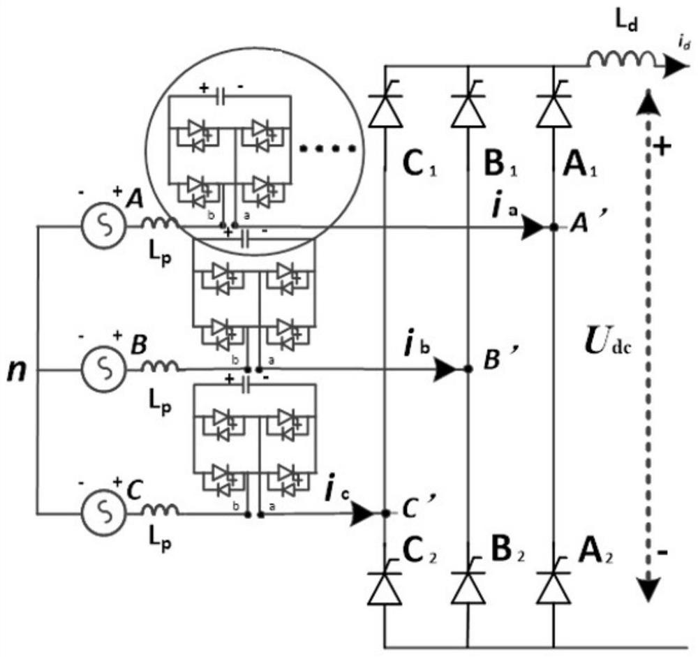
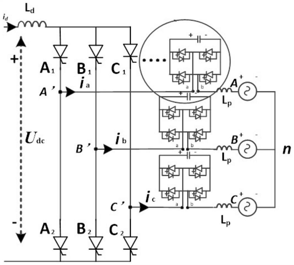
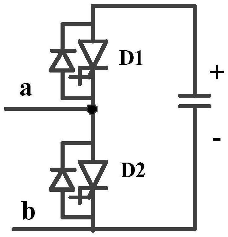
[0030] This embodiment provides a modular capacitor-commutated converter, such as figure 1 (rectification mode) and figure 2 (inversion mode), including: a three-phase six-pulse converter valve and a capacitor module; the three-phase six-pulse converter valve is connected in series with the capacitor module, and the capacitor module is set between the converter transformer and the three-phase six-pulse converter valve between, figure 1 and figure 2 The converter transformer in is characterized by its secondary side voltage; the capacitor module includes a capacitor and at least one group of converter bridges composed of sub-modules composed of reverse-parallel diodes that can turn off power electronic devices, and the converter bridge is connected in parallel with the capacitor.
[0031] In this embodiment, a capacitor module is introduced, and its voltage provides an auxiliary commutation voltage for the commutation of the thyristor of the LCC converter valve, which relaxes...
Embodiment 2
[0039] Based on the same inventive concept, this embodiment discloses a modularized capacitor-commutated commutation method, which is implemented by using any of the modularized capacitor-commutated converters in Embodiment 1, wherein the X-phase and Y-phase are both One of Phase A, Phase B and Phase C.
[0040] When the converter operates in rectification mode, such as figure 1 As shown, at the high potential, the phase X is switched to the Y phase, and the line voltage U Y-X Before the natural commutation point P, turn on the capacitor modules connected in the X-phase and Y corresponding circuits, connect the capacitor modules in series in the positive direction of the Y-phase, and increase the voltage on the AC side of the thyristor valve Y1, that is, the voltage at point Y'. The X phase is reversely connected to the capacitor module in series to reduce the voltage on the AC side of the thyristor valve X1, that is, the voltage at point X', so that the relative voltage valu...
Embodiment 3
[0048]This embodiment takes a specific case applied to the sending end of a typical ±800kV, 8000MW LCC UHV DC project as an example to specifically illustrate the technical solutions in Embodiment 1 and Embodiment 2.
[0049] It is known that the ±800kV, 8000MWLCC UHV DC project adopts a bipolar structure with two twelve-pulse converter valves per pole, a total of four six-pulse converter structures, and the inductive voltage drop of the converter transformer at the sending end is set at 10.5%. The rated firing angle is taken as 15° according to engineering experience, then the ideal no-load DC voltage U of each six-pulse converter at the sending end dio It is 233.5kV.
[0050] Converter valve side AC voltage line voltage It is 172.9kV.
[0051] The design goal is to transform the LCC converter into a modular capacitor-commutated converter, so that the reactive power consumption at the sending end is zero.
[0052] The traditional LCC converter is triggered at 15°, and the...
PUM
 Abstract
Description
Claims
Application Information
 - R&D
- Intellectual Property
- Life Sciences
- Materials
- Tech Scout
- Unparalleled Data Quality
- Higher Quality Content
- 60% Fewer Hallucinations
Browse by: Latest US Patents, China's latest patents, Technical Efficacy Thesaurus, Application Domain, Technology Topic, Popular Technical Reports.
© 2025 PatSnap. All rights reserved.Legal|Privacy policy|Modern Slavery Act Transparency Statement|Sitemap|About US| Contact US: help@patsnap.com


