Layered grouting freezing device and layered grouting freezing method

A technology of freezing device and grouting, which is applied in basic structure engineering, construction, soil protection, etc. It can solve the problems that the grouting position is not targeted and affects the effect of soil reinforcement and groundwater layer water-stopping, etc., and achieves the convenience of transportation Effect

Active Publication Date: 2022-04-19
ANHUI UNIVERSITY OF ARCHITECTURE
View PDF1 Cites 0 Cited by
  • Summary
  • Abstract
  • Description
  • Claims
  • Application Information

AI Technical Summary

Problems solved by technology

However, the above-mentioned double-pipe annular grouting freezing pipe can only be grouted through the drill bit, and the grouting position is not targeted, which affects the effect of soil reinforcement and groundwater layer water stop

Method used


Image

  • Layered grouting freezing device and layered grouting freezing method
  • Layered grouting freezing device and layered grouting freezing method
  • Layered grouting freezing device and layered grouting freezing method

Examples


specific Embodiment 1

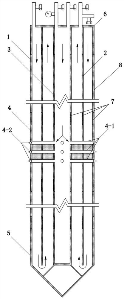
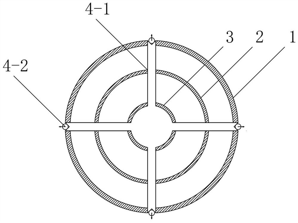
[0055] Such as figure 1 As shown, the layered grouting freezing device includes a layered grouting pipeline, and the layered grouting pipeline includes a liquid return pipe 2, a grouting pipe 3 and a freezing pipe 1, and the grouting pipe 3, the liquid returning pipe 2 and the freezing pipe 1 are from They are arranged sequentially from inside to outside to form concentric cylinders, and the bottom of the grouting pipe 3 is closed. Such as Figure 4 As shown, the bottom of the layered grouting pipeline is provided with a drill bit 5, and the drill bit 5 is arranged on the bottom of the layered grouting pipeline through a threaded connection. The drill bit 5 has a return cavity 5-1, and the return pipe 2 and the freezing pipe 1 are all Connected with the return chamber 5-1, the freezing pipe 1, the return chamber 5-1 and the liquid return pipe 2 form a low-temperature freezing liquid flow channel.

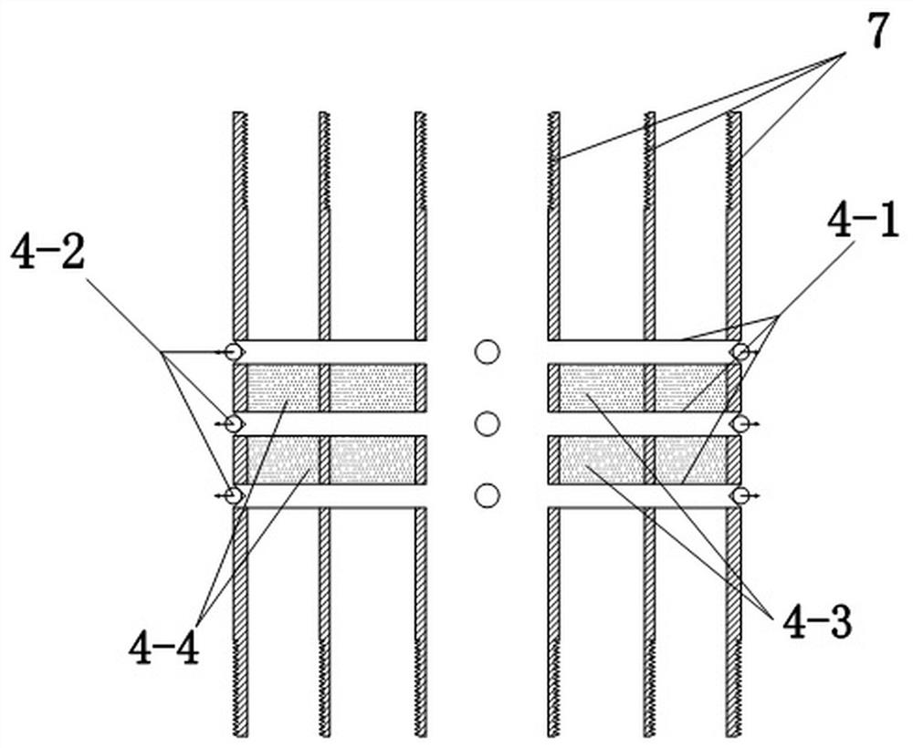
[0056] Such as figure 2 with image 3 As shown, the layered grouting pipel...

specific Embodiment 2

[0066] Specific embodiment 2 of the layered grouting freezing device of the present invention: The difference between this embodiment and specific embodiment 1 is that in specific embodiment 1, the layered grouting pipe grouting pipeline adopts the first pipeline monomer and the second The form of arrangement and combination of pipeline monomers. In this embodiment, the layered grouting pipe grouting pipeline does not include the first pipeline monomer, and is formed by connecting the second pipeline monomers in sequence. At this time, the injection of the layered grouting freezing device The performance of slurry reinforcement is better, but the amount of slurry used is larger.

specific Embodiment 3

[0067] Specific embodiment 3 of the layered grouting freezing device of the present invention: The difference between this embodiment and specific embodiment 1 is that, in specific embodiment 1, the layered grouting pipes and the grouting pipes are sequentially grouting pipes from inside to outside , liquid return pipe and freezing pipe, and the grouting pipe, liquid return pipe and freezing pipe constitute concentric cylinders. In this embodiment, the grouting pipe, liquid returning pipe and freezing pipe form concentric cylinders, but the grouting pipe Between the liquid tube and the freezing tube.


PUM


Abstract

The invention provides a layered grouting freezing device and a layered grouting freezing method. The layered grouting freezing device includes: a layered grouting pipeline, and the layered grouting pipeline includes a liquid return pipe, a grouting pipe and a freezing pipe; The layered grouting pipeline includes a plurality of pipeline monomers, at least a part of the pipeline monomers are provided with grout pipes, the grout pipes communicate with the outside of the layered grouting pipeline and the grouting pipes, and the grout pipes are provided with non-return devices. According to the address exploration data, the present invention can directly set the grout pipe on the pipeline monomer corresponding to the groundwater layer, and can carry out grouting for the groundwater layer when the soil body is pre-reinforced before freezing and when the soil body is reinforced after grouting. Injection can better ensure the effect of soil reinforcement and water-stopping of groundwater layer.

Description

technical field [0001] The invention belongs to the technical field of freezing equipment, and in particular relates to a layered grouting freezing device and a layered grouting freezing method. Background technique [0002] Artificial formation freezing technology is to drill a certain number of freezing holes around the underground space to be excavated before underground engineering construction, and install a freezer in the freezing hole so that the low-temperature freezing liquid flows in the freezer and absorbs the surrounding area of ​​the freezer. The heat of the stratum, thus freezing the water in the stratum into ice: turning the natural soil into frozen soil, and cutting off the groundwater, forming a frozen cylinder in the loose, water-bearing and unstable stratum, and the frozen cylinder gradually expands and connects into a closed, A cylinder (ie, frozen circle) that meets the design thickness and strength ensures subsequent safe and reliable sinking constructi...

Claims


Application Information

Patent Timeline
Patent Type & Authority Patents(China)
IPC IPC(8): E02D3/115E02D15/02
CPCE02D3/115E02D15/02E02D2250/003
Inventor 林键程桦彭世龙曹广勇董聪邓文杰谭诗宏
Owner ANHUI UNIVERSITY OF ARCHITECTURE
Why Eureka
Try Eureka