Piston type retarding braking system for truck
A slow-speed braking, piston-type technology, used in brake actuators, gear transmission mechanisms, mechanical equipment, etc., can solve the problems of brake recession, poor heat dissipation, and reduced braking efficiency, and reduce lock-up. , Improve braking effect, increase the effect of resistance
- Summary
- Abstract
- Description
- Claims
- Application Information
AI Technical Summary
Problems solved by technology
Method used
Image
Examples
Embodiment 1
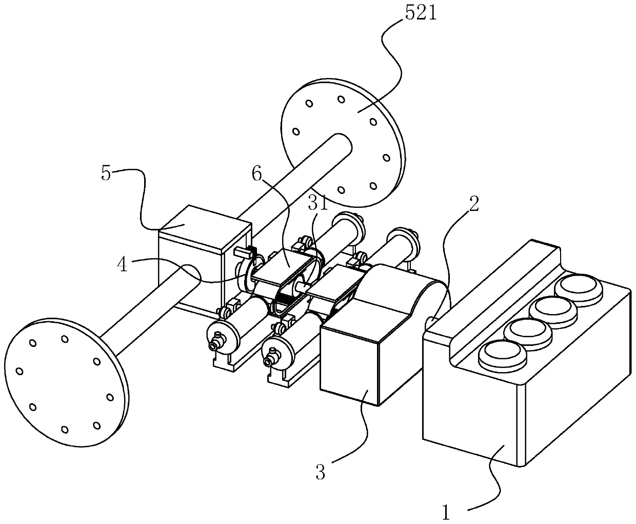
[0041] Embodiment 1: A kind of piston-type retarding braking system for trucks, including engine 1, power shaft 2 driven by engine 1, gearbox 3, transmission shaft 31 for outputting the changed speed of gearbox 3, setting The disc brake 4 on the transmission shaft 31 , the rear axle 5 arranged at the end of the power shaft 2 away from the engine 1 , and the piston brake 6 for braking by the transmission shaft 31 . The rear axle 5 is provided with a connection disc 521 connected with the tire.
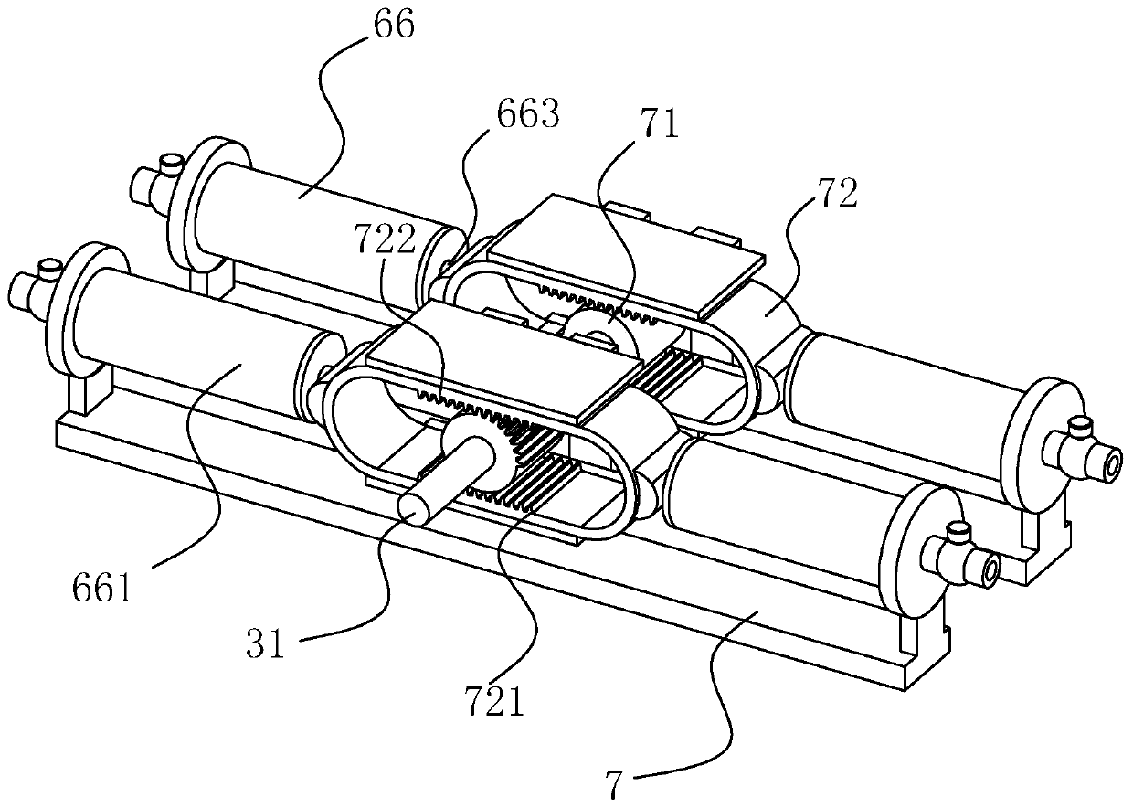
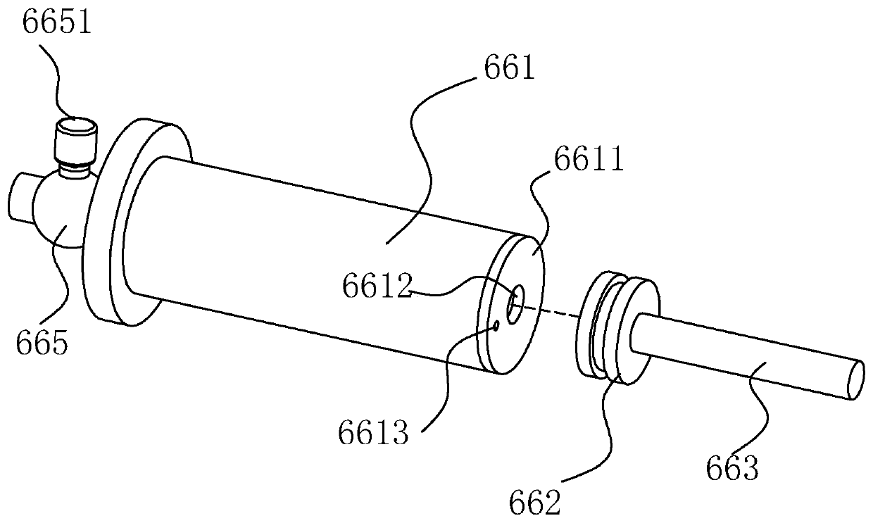
[0042] see figure 2 and image 3 , The piston brake 6 includes a frame body 7 fixed on the vehicle body and a piston 66 fixed on the frame body 7 .
[0043] The transmission shaft 31 is provided with a missing gear 71 coaxially rotating with the transmission shaft 31 (keyway connection), and the periphery of the missing gear 71 is provided with a moving frame 72 that cooperates with the missing gear 71. The top and bottom ends of the inner wall of the moving frame 72 are respectively...
Embodiment 2
[0050] Embodiment 2: The difference between this embodiment and Embodiment 1 lies in the way of driving the piston rod 663 to reciprocate.
[0051] A piston retarder braking system for trucks, see Figure 4 , including an engine 1, a power shaft 2 driven by the engine 1, a gearbox 3, a disc brake 4 arranged between the gearbox 3 and the engine 1, a rear axle 5 arranged at the end of the power shaft 2 away from the engine 1, and the rear Bridge 5 is braked by piston brake 6 . There are two groups of piston brakes 6, which are symmetrically arranged at both ends of the rear axle 5. The number of disc brakes 4 is two, and the control end extends into the cab of the truck.
[0052] The gearbox 3 is provided with a transmission shaft 31 , the power shaft 2 transmits the power of the engine 1 to the gearbox 3 , and after the gearbox 3 rotates, it is output through the transmission shaft 31 .
[0053] see Figure 4 and Figure 5 , the rear axle 5 includes a housing 51 fixed to t...
Embodiment 3
[0063] Embodiment 3: The difference between this embodiment and Embodiment 1 is that the braking position of the piston brake 6 is different.
[0064] see Figure 5 and Figure 6 , the left output shaft 53 (and the right output shaft 52) is provided with a fourth brake gear 68 coaxially rotating with the left output shaft 53 (and the right output shaft 52), and the first brake gear 61 and the fourth brake gear Gear 68 meshes. A housing 69 for supporting the first brake gear 61 , the brake shaft 62 and the second brake gear 63 is fixed on the housing 51 . At this time, the resistance of the piston 66 is directly transmitted to the left output shaft 53 (and the right output shaft 52 ), which directly decelerates and brakes the left output shaft 53 (and the right output shaft 52 ).
PUM
 Abstract
Description
Claims
Application Information
 - R&D
- Intellectual Property
- Life Sciences
- Materials
- Tech Scout
- Unparalleled Data Quality
- Higher Quality Content
- 60% Fewer Hallucinations
Browse by: Latest US Patents, China's latest patents, Technical Efficacy Thesaurus, Application Domain, Technology Topic, Popular Technical Reports.
© 2025 PatSnap. All rights reserved.Legal|Privacy policy|Modern Slavery Act Transparency Statement|Sitemap|About US| Contact US: help@patsnap.com


