

Laser demarcation device
A laser line throwing instrument and laser technology, applied in the field of laser line throwing instrument, can solve the problems of reduced precision, inconvenient use, unadjustable breakpoint position, etc., and achieve the effects of improved precision, convenient use and simple structure
- Summary
- Abstract
- Description
- Claims
- Application Information
AI Technical Summary
Problems solved by technology
Method used
Image

Examples
Embodiment 1
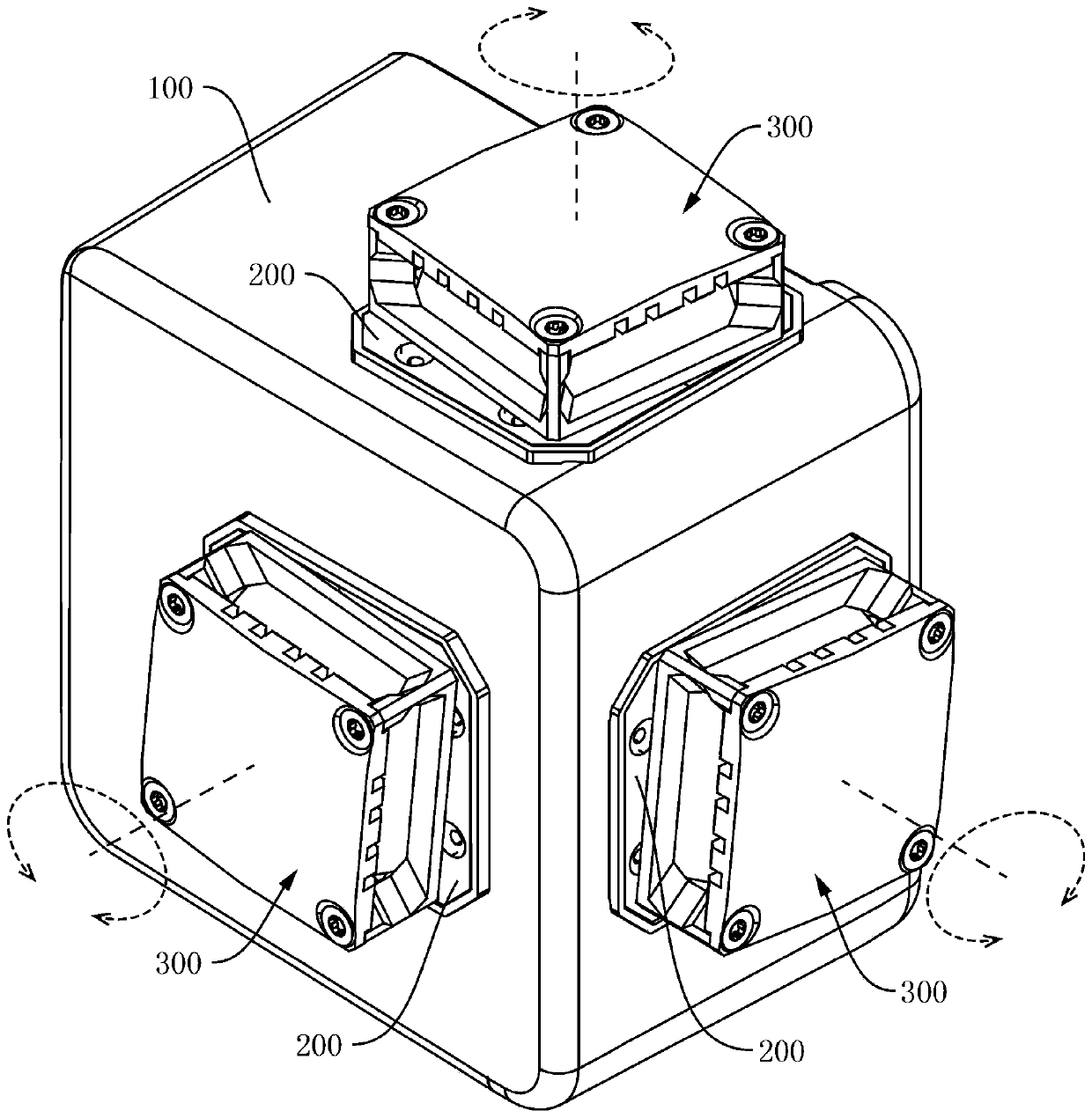
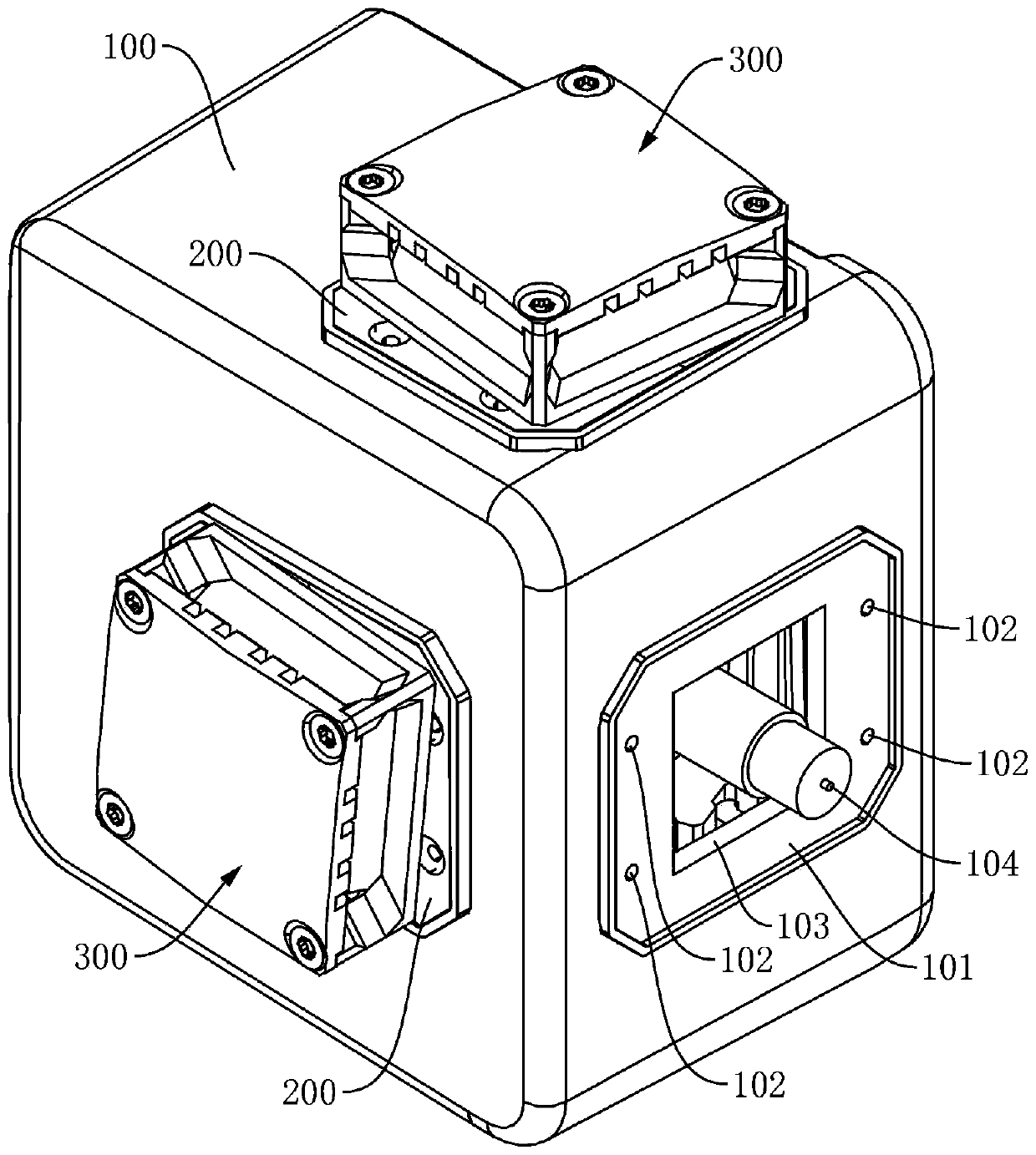
[0042] see Figure 1-Figure 8 , the present embodiment provides a laser line projector, including a housing 100, the housing 100 can adopt the existing shape, for example, a rectangular parallelepiped structure can be preferred, such as figure 1 and figure 2 As shown, the housing 100 is provided with a laser window 103 for emitting laser light and a window cover 300 for covering the laser window 103. The window cover 300 is movably arranged on the housing 100 and can be positioned relative to the housing. The body 100 rotates, as shown in the figure, the number of the laser window 103 and the window cover 300 can be determined according to actual needs, usually 1-3, as an example, as figure 1 and figure 2 As shown, in this embodiment, the casing 100 is provided with three laser windows 103, and a window cover 300 is respectively movably arranged at the three laser windows 103, and the three window covers 300 are respectively arranged on the casing 100 on three surfaces pe...
Embodiment 2
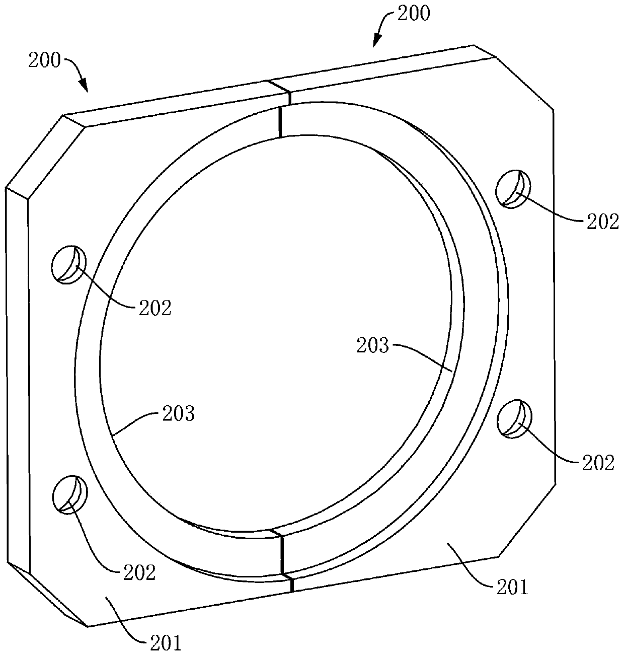
[0052] In order to solve the positioning problem of the constraining component 200, the main difference between the second embodiment and the first embodiment is that, in the laser line thrower provided by this embodiment, the housing 100 is provided with a positioning groove 101, and the connecting part 201 The shape of the connecting part 201 is adapted to the shape of the positioning groove 101. Since the shape of the connecting part 201 is suitable for the shape of the positioning groove 101, as in the same way, when the constraining part 200 is installed, it is only necessary to snap the connecting part 201 into the corresponding positioning groove 101 In this way, the positioning of the constraining component 200 can be realized, so that the protrusion 203 configured on the connecting portion 201 can snap into the predetermined depth and predetermined position of the locking groove 305, thereby effectively solving the positioning problem of the constraining component 200, ...
Embodiment 3
[0055] In order to solve the problem of assembling and assembling the window cover 300, the main difference between this embodiment 3 and embodiment 1 or embodiment 2 is that in the laser line projection instrument provided by this embodiment, the window cover 300 includes a window frame 301, The light-transmitting member 306 and the window cover 307, such as Figure 4-Figure 8 As shown, the window frame 301 includes a base 302 and at least three connecting columns 303 constructed on the same side of the base 302, the window cover 307 is detachably fixed to the connecting columns 303, and is on the side of the window frame 301 Enclose at least three windows for passing the laser line. As an example, in this embodiment, the base 302 is provided with four connecting columns 303, and the window cover 307 is fixed to the connecting columns 303 by bolts 308, as Image 6 as shown, so as to enclose four windows;
[0056] The light-transmitting member 306 is arranged between the base...
PUM
 Abstract
Description
Claims
Application Information