
Three-dimensional solid modeling method for non-circular gear pair with involute tooth profile

A technology of non-circular gears and involute teeth is applied in the field of three-dimensional solid modeling of non-circular gear pairs. The drawing process is simple, the development difficulty is small, and the drawing is convenient.

Active Publication Date: 2020-08-14
XIAN AERONAUTICAL UNIV
View PDF3 Cites 0 Cited by
  • Summary
  • Abstract
  • Description
  • Claims
  • Application Information

AI Technical Summary

Problems solved by technology

[0003] (1) Converted tooth profile method: The core idea of ​​the converted tooth profile method is to convert each tooth of a non-circular gear into the tooth profile of an equivalent circular gear. This method is an approximate design method, which is difficult to meet the high-precision transmission ratio requirements
[0004] (2) Tooth profile normal method: The tooth profile normal method is a drawing method. In order to obtain an accurate tooth profile, it is necessary to make enough The normal of the tooth shape makes the modeling process too cumbersome
[0005] (3) Analytical method: The analytical method is based on the principle of gear meshing, constructs the tooth profile equation, calculates the data point coordinates of the tooth profile, and uses it in the 3D modeling software according to The data point coordinates are used to establish the tooth profile curve, and stretching is formed on this basis. The calculation process of this method is more complicated.
[0007]In summary, the existing design methods require cumbersome calculations and drawings, which largely limits the application of non-circular gears

Method used


Image

  • Three-dimensional solid modeling method for non-circular gear pair with involute tooth profile
  • Three-dimensional solid modeling method for non-circular gear pair with involute tooth profile
  • Three-dimensional solid modeling method for non-circular gear pair with involute tooth profile

Examples


Embodiment Construction

[0051] The present invention will be described in further detail below in conjunction with specific examples, but not as a limitation of the present invention.

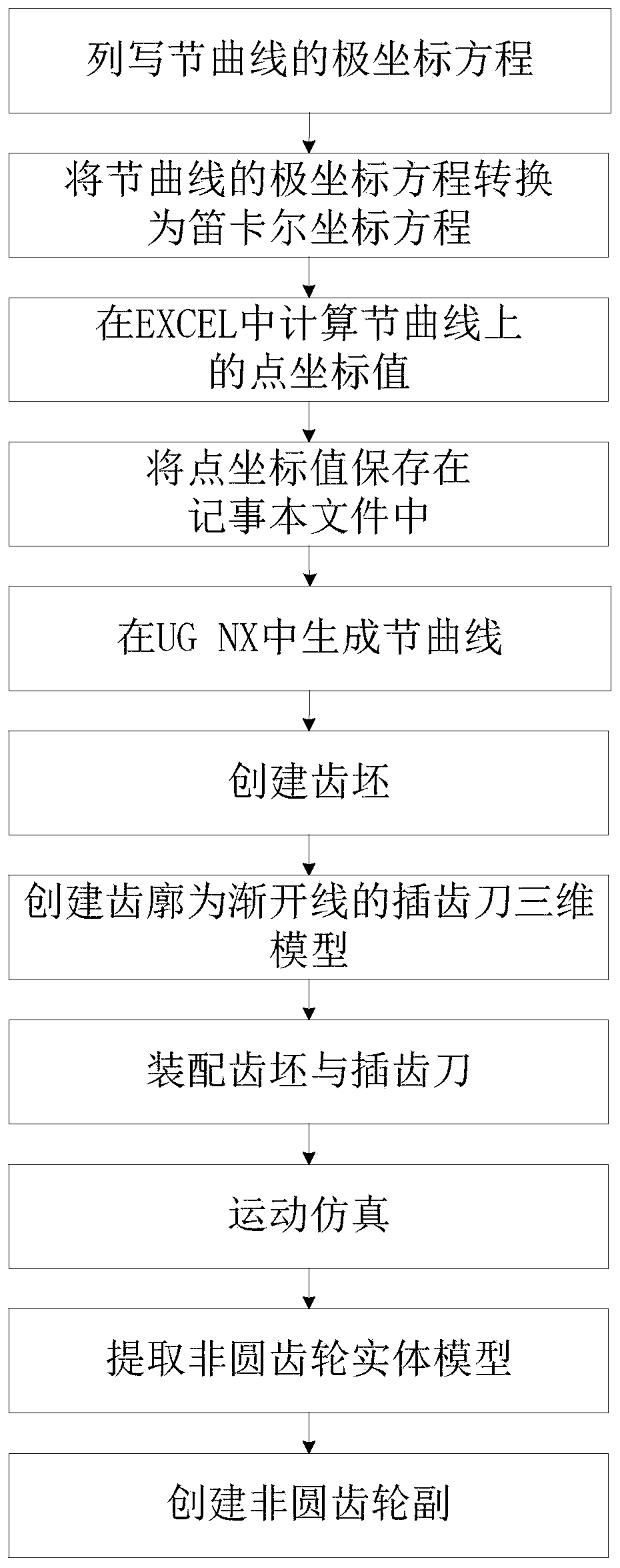
[0052] Such as figure 1 As shown, the non-circular gear pair three-dimensional solid modeling method of the involute tooth profile of the present invention comprises the following steps:

[0053] (1) Set the center distance between the driving wheel and the driven wheel and the transmission ratio function, and list the equations of the driving wheel and the driven wheel in the polar coordinate system

[0054] For example, set the center distance as a=50mm

[0055] The transmission ratio function is i 21 =1-0.5cosφ 1 , φ1 ∈[0,2π]

[0056] Among them, φ 1 is the driving wheel angle

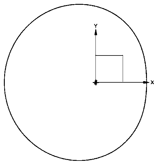
[0057] Then in the polar coordinate system, the pitch curve equation of the drive wheel is:

[0058]

[0059] Among them, r 1 Radius of driving wheel

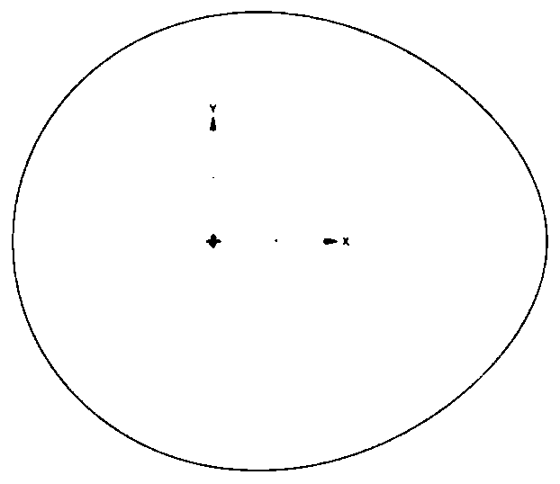
[0060] The pitch curve equation of the driven wheel is:

[0061]

[0062...


PUM


Abstract

The invention discloses a three-dimensional solid modeling method for a non-circular gear pair with an involute tooth profile. The method includes: according to a transmission ratio function and a center distance, obtaining point coordinate values on pitch curves of a driving wheel and a driven wheel in the non-circular gear pair in an EXCEL table; importing the point coordinate values into UG NXsoftware to obtain a driving wheel pitch curve and a driven wheel pitch curve, creating a gear blank on the basis of the driving wheel pitch curve and the driven wheel pitch curve, and obtaining a solid model of the non-circular gear by defining the initial positions and relative movement of the gear blank and the slotting cutter model and adopting a motion simulation means, so as to enble the obtained three-dimensional model transmission precision to be superior to that of a tooth profile conversion method. The modeling process is simple, no complex calculation process exists, and the calculation amount is small; a three-dimensional model of the non-circular gear pair is obtained by adopting a UG NX motion simulation technology, programming is carried out without designing an algorithm, and the development difficulty is low.

Description

technical field [0001] The invention belongs to the field of mechanical design and relates to a three-dimensional solid modeling method of a non-circular gear pair with an involute tooth profile. Background technique [0002] Non-circular gear is a special mechanical transmission part, which can realize nonlinear motion and power transmission. The structure of non-circular gears is complex, and it is difficult to create a 3D solid model of non-circular gear pairs. The existing 3D modeling methods for non-circular gears are as follows: [0003] (1) Converted tooth profile method: The core idea of ​​the converted tooth profile method is to convert each tooth of a non-circular gear into the tooth profile of an equivalent circular gear. This method is an approximate design method, which is difficult to meet high-precision transmission than demand. [0004] (2) Tooth profile normal method: The tooth profile normal method is a drawing method. In order to obtain an accurate tooth...

Claims


Application Information

Patent Timeline
IPC IPC(8): G06F30/17F16H55/08
CPCG06F30/17F16H55/0806F16H55/084F16H2057/0087
Inventor 史诺张雪宁刘琼
Owner XIAN AERONAUTICAL UNIV
Learn More