Magnetic random access memory unit and data writing method thereof

A random storage and data writing technology, applied in information storage, static memory, digital memory information, etc., can solve the problems of low storage density, large critical switching current, and large power consumption

Active Publication Date: 2020-08-14
BEIHANG UNIV
View PDF8 Cites 5 Cited by
  • Summary
  • Abstract
  • Description
  • Claims
  • Application Information

AI Technical Summary

Problems solved by technology

However, the spin-orbit moment writing method requires an external magnetic field in the in-plane direction, which will increase the complexity of the circuit. If an antiferromagnetic (Antiferromagnetic, AFM) film is used to generate an exchange bias field (Exchange Bias Field, EB) replaces the external magnetic field to achieve non-magnetic field switching. Since the generated EB is small, the critical switching current is large and the power consumption is large
And the storage unit of SOT-MRAM has three ports, and each MTJ needs to have two access control first transistors, and the storage density is low

Method used


Image

  • Magnetic random access memory unit and data writing method thereof
  • Magnetic random access memory unit and data writing method thereof
  • Magnetic random access memory unit and data writing method thereof

Examples


Embodiment 1

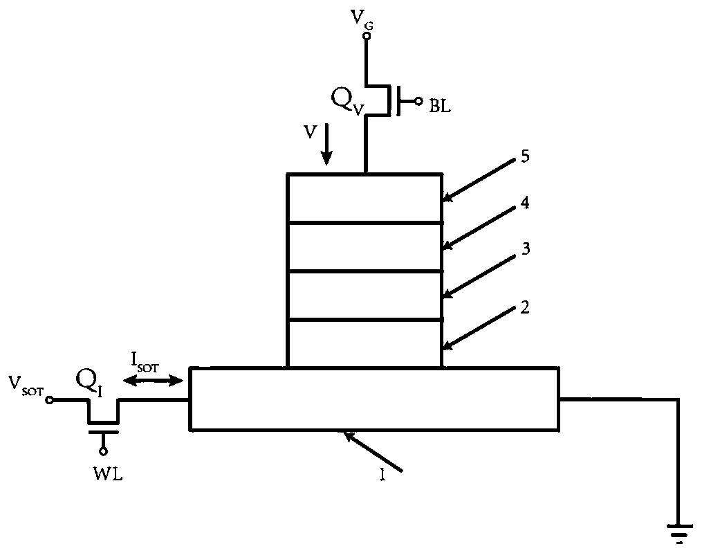
[0052] In order to solve the above problems, according to one aspect of the present invention, this embodiment discloses a data writing method for a magnetic random access memory unit. Wherein, the magnetic random memory unit includes a spin-orbit moment layer 1 and at least one magnetic tunnel junction disposed on the spin-orbit moment layer 1. In this embodiment, a magnetic tunnel junction is taken as an example for illustration, as shown in figure 1 As shown, in other embodiments, multiple magnetic tunnel junctions may also be provided. The magnetic tunnel junction includes a reference layer 4 , a barrier layer 3 and a free layer 2 arranged from top to bottom, and the bottom surface of the free layer 2 is fixed in contact with the upper surface of the spin-orbit moment layer 1 . Preferably, a synthetic antiferromagnetic layer and a top electrode 5 can be added on the reference layer 4 .

[0053] Taking the MTJ with in-plane magnetic anisotropy as an example, as figure 2 ...

Embodiment 2

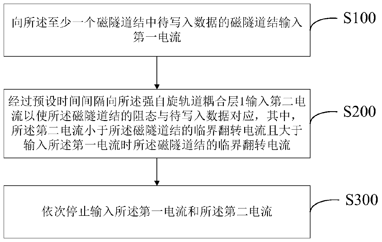
[0096] In this embodiment, different from Embodiment 1, the magnetic random access memory unit of this embodiment includes a spin-orbit moment layer 1 and a plurality of magnetic tunnel junctions fixed on the spin-orbit moment layer 1, and a plurality of magnetic tunnel junctions An array of magnetic tunnel junctions is formed. When writing data into one or more of the magnetic tunnel junction arrays, similar to Embodiment 1, a selection voltage is input to a magnetic tunnel junction to be written with data among the plurality of magnetic tunnel junctions. Then, a write current is input into the spin-orbit moment layer 1 after a preset time interval so that the resistance state of the magnetic tunnel junction corresponds to the data to be written, wherein the write current is smaller than that of the magnetic tunnel junction The critical switching current is greater than the critical switching current of the magnetic tunnel junction when the selection voltage is input. Finall...


PUM


Abstract

The invention provides a magnetic random access memory unit and a data writing method thereof. The magnetic random access memory unit comprises a spin orbital moment layer and at least one magnetic tunnel junction arranged on the spin orbital moment layer. The data writing method comprises: inputting a selection voltage to a magnetic tunnel junction of to-be-written data in the at least one magnetic tunnel junction; inputting writing current into the spin orbit moment layer at a preset time interval to enable the resistance state of the magnetic tunnel junction to correspond to-be-written data, wherein the writing current is smaller than the critical overturning current of the magnetic tunnel junction and larger than the critical overturning current of the magnetic tunnel junction when theselection voltage is input; and stopping inputting the selection voltage and the writing current in sequence. According to the method, deterministic overturning of the magnetic tunnel junction magnetic moment can be ensured, and the storage density is improved.

Description

technical field [0001] The invention relates to the technical field of magnetic memory, in particular to a magnetic random memory unit and a data writing method thereof. Background technique [0002] With the continuous shrinking of semiconductor process dimensions, Moore's Law slows down, and the increase of leakage current and interconnection delay become the bottleneck of traditional CMOS memory. Finding the solution of the new generation memory technology has become the focus of integrated circuit research, and the magnetic random access memory unit has received extensive attention. Compared with traditional devices, Magnetic Random Access Memory (MRAM) has the advantages of unlimited erasing times, non-volatility, fast read and write speed, and radiation resistance. Ideal for volatile memory and in-memory computing. [0003] For a long time, the writing mechanism has been the main technical bottleneck restricting the development of MRAM. Currently, the mainstream ele...

Claims


Application Information

Patent Timeline
IPC IPC(8): G11C11/16H01L43/08
CPCG11C11/1675H10N50/10
Inventor 赵巍胜彭守仲李伟祥芦家琪
Owner BEIHANG UNIV
Why Eureka
Try Eureka