Horizontal air chamber flash evaporation dryer for sludge drying

A flash dryer and sludge drying technology, applied in the direction of dewatering/drying/concentrating sludge treatment, etc., can solve the problems of increasing the unit disposal cost of sludge, the failure of the dryer to operate normally, and the large resistance of the flash dryer, etc. Achieve the effect of eliminating sludge sticking to the wall, reducing power consumption and reducing resistance

Inactive Publication Date: 2020-08-18
SOUTHEAST UNIV
View PDF7 Cites 1 Cited by
  • Summary
  • Abstract
  • Description
  • Claims
  • Application Information

AI Technical Summary

Problems solved by technology

[0002] Traditional flash dryers are widely used in industrial production, but the sludge has a high moisture content, especially when the sludge has a moisture content of 50-60%, and the viscosity is high, so that the traditional flash dryer cannot be used for sludge drying. Stable operation, such as sludge is easy to deposit at the bottom of the dryer, blocking the inlet of the drying medium, causing the dryer to fail to operate normally. In addition, the traditional flash dryer has high resistance, which leads to high power consumption during the operation of the drying system and increases pollution. Unit Disposal Cost of Mud

Method used


Image

  • Horizontal air chamber flash evaporation dryer for sludge drying
  • Horizontal air chamber flash evaporation dryer for sludge drying

Examples


Embodiment 1

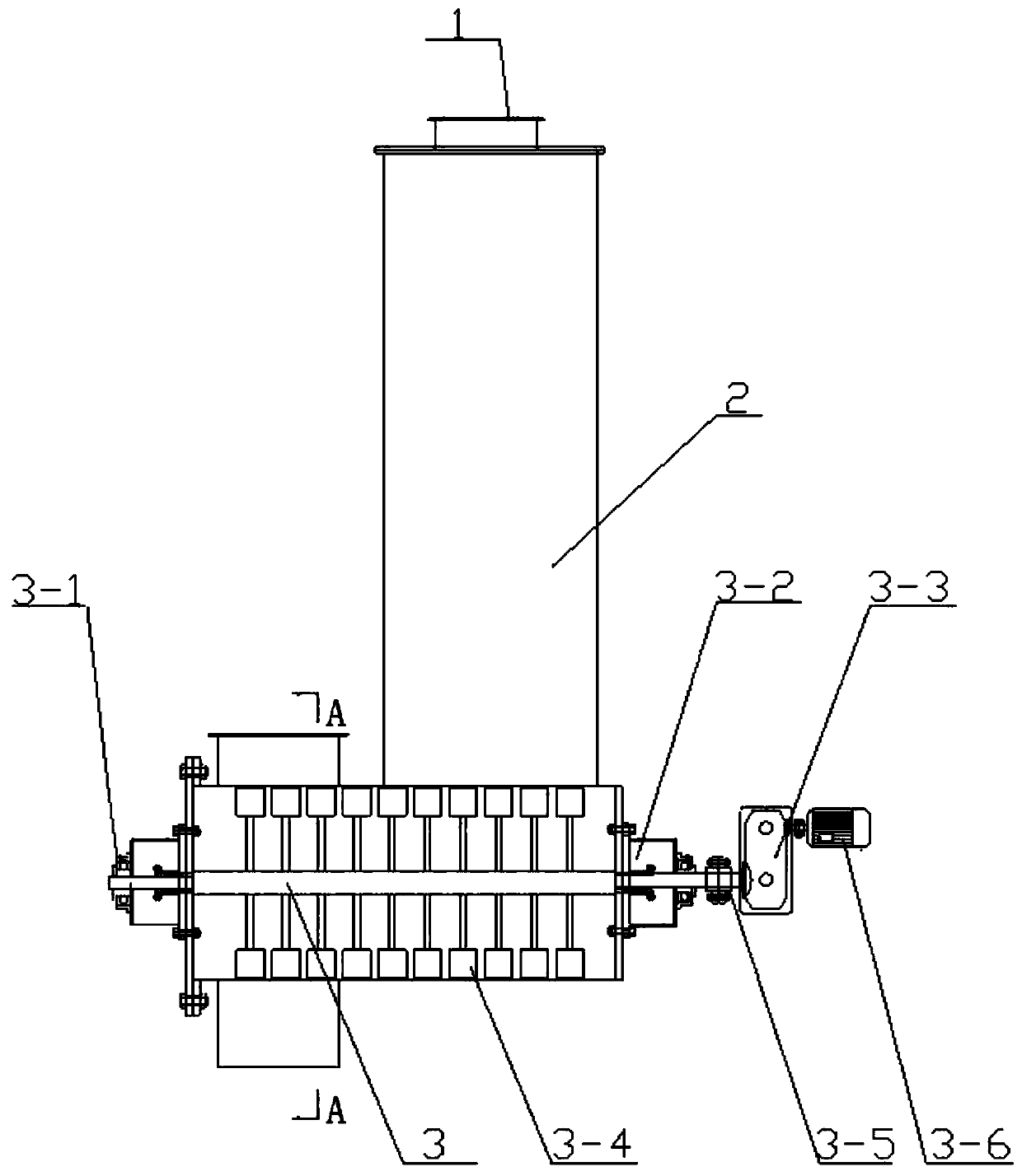
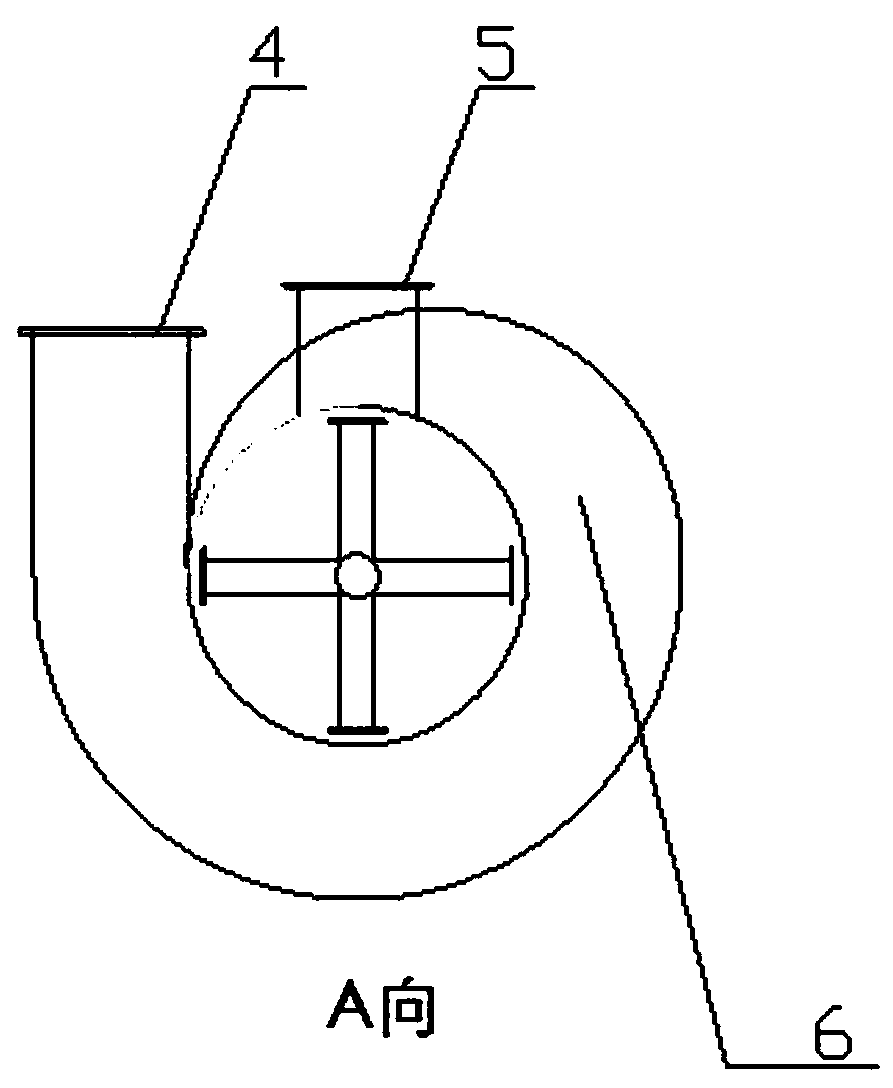
[0020] Such as figure 1 , figure 2 Shown is a horizontal air chamber flash dryer for sludge drying. The dryer includes a drying tower (2), a horizontal stirring device (3), and a horizontal air chamber (6); the horizontal stirring device (3) is connected to the horizontal air chamber (6), and the horizontal stirring device ( 3) Including stirring shaft, left bearing seat (3-1), right bearing seat (3-2), reducer (3-3), lifting plate (3-4), coupling (3-5), motor (3-6); the stirring shaft is provided with a lifting plate, and one end of the stirring shaft is fixedly connected to the housing of the horizontal air chamber (6) through the left bearing seat (3-1); the other end of the stirring shaft One end is connected to the housing of the horizontal air chamber (6) through the right bearing seat (3-2), the stirring shaft is connected to the reducer (3-3) through the coupling (3-5), and the reducer (3 -3) Connect the motor (3-6); the top of the horizontal air chamber (6) is con...


PUM


Abstract

The invention discloses a horizontal air chamber flash evaporation dryer for sludge drying. The horizontal air chamber flash evaporation dryer comprises a drying tower, a horizontal air chamber and ahorizontal stirring device; the horizontal stirring device is composed of a left bearing seat, a right bearing seat, a speed reducer, a motor, a shoveling plate and a coupler; a sludge feeding port and a heat medium inlet are formed in the horizontal air chamber of the dryer, and a drying medium and dry sludge outlet is formed in the drying tower. Wet sludge is fed into the improved horizontal airchamber of the flash evaporation dryer through a feeding port, a heat medium tangentially enters the horizontal air chamber from one end of the horizontal air chamber, the wet sludge and the heat medium are in full contact in the horizontal air chamber of the dryer under the action of the shoveling plate, and water in the wet sludge is quickly evaporated into dry sludge and leaves the drying tower along with the cooled heat medium. The dry sludge leaving the drying device enters a trapping device, and the purified tail gas is directly discharged into the atmosphere.

Description

technical field [0001] The invention relates to the field of sludge dryers, in particular to a horizontal air chamber flash dryer for sludge drying. Background technique [0002] Traditional flash dryers are widely used in industrial production, but the sludge has a high moisture content, especially when the sludge has a moisture content of 50-60%, and the viscosity is high, so that the traditional flash dryer cannot be used for sludge drying. Stable operation, such as sludge is easy to deposit at the bottom of the dryer, blocking the inlet of the drying medium, causing the dryer to fail to operate normally. In addition, the traditional flash dryer has high resistance, which leads to high power consumption during the operation of the drying system and increases pollution. The unit disposal cost of mud. Therefore, the present invention improves the design of the traditional flash dryer, improves the air chamber and the stirring device in the air chamber of the traditional fl...

Claims


Application Information

Patent Timeline
Patent Type & Authority Applications(China)
IPC IPC(8): C02F11/13
CPCC02F11/13
Inventor 郭宏伟鲁维加
Owner SOUTHEAST UNIV
Why Eureka
Try Eureka