Optical fiber high-speed drawing ultraviolet curing device

A curing device and high-speed technology, which is applied in the field of optical fiber processing, can solve the problems of inability to cure with ultraviolet rays and lack of dust-proof measures, so as to improve the light receiving efficiency, improve the curing effect, and ensure the curing effect.

Pending Publication Date: 2020-08-18
SHENZHEN INSTITUTE OF INFORMATION TECHNOLOGY
View PDF0 Cites 0 Cited by
  • Summary
  • Abstract
  • Description
  • Claims
  • Application Information

AI Technical Summary

Problems solved by technology

However, this application simply passes the optical fiber through a pipeline filled with nitrogen gas, and cannot perform effective all-round UV curing, and uses air pumping to replace

Method used


Image

  • Optical fiber high-speed drawing ultraviolet curing device
  • Optical fiber high-speed drawing ultraviolet curing device
  • Optical fiber high-speed drawing ultraviolet curing device

Examples


Example Embodiment

[0043] Example 1

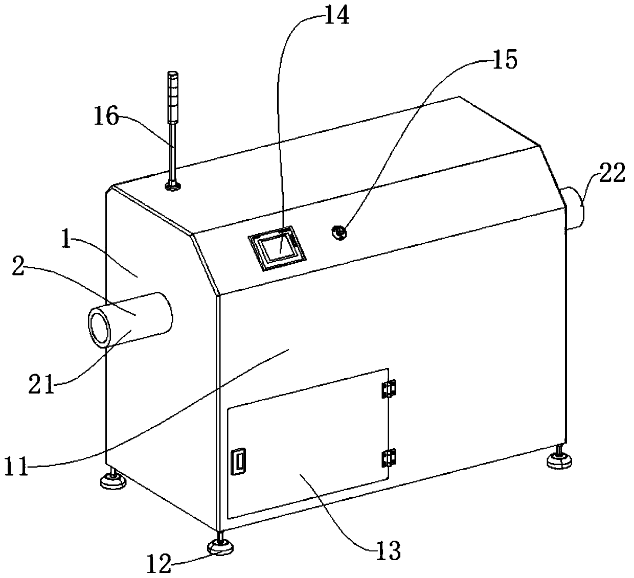
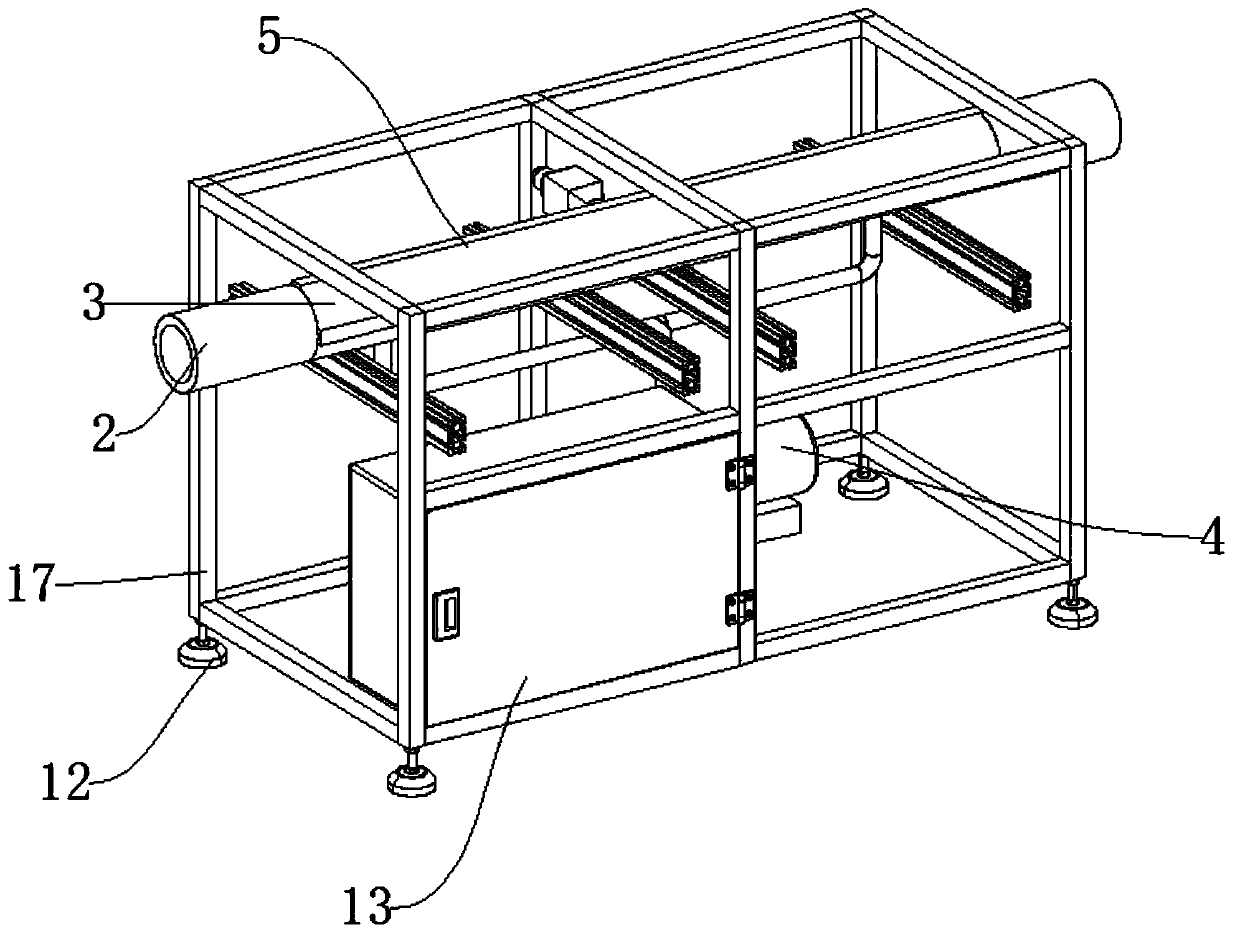
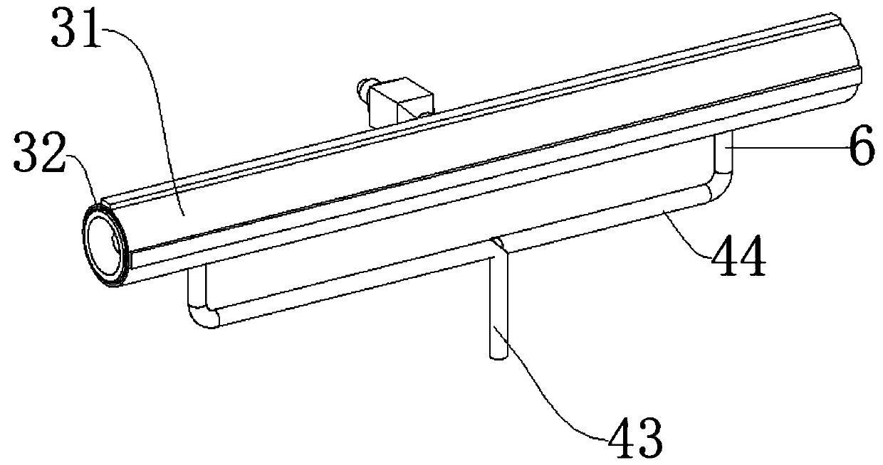
[0044] like Figure 1-Figure 7 As shown, the connection mechanism 6 includes a straight air nozzle 61 and an air outlet hole 62. The straight air nozzle 61 is connected to the transparent barrel 32 of the sealing transmission mechanism 3 through a sealing ring, and the other end of the straight air nozzle 61 is connected to the transmission of the air source mechanism 4 through a thread. The pipe 44 and the air outlet hole 62 are arranged between the transparent barrel 32 of the sealed transmission mechanism 3 and the air outlet pipe 45 of the air source mechanism 4. After the transfer pipe 44 transmits nitrogen to the two straight air nozzles 61, the straight air nozzle 61 Nitrogen gas is filled into the transparent barrel 32 to replace the waste gas produced by curing inside the transparent barrel 32, and the waste gas is discharged through the air outlet 62; the support mechanism 1 includes a protective shell 11, a shock absorber 12, and a storage box 13 ...

Example Embodiment

[0045] Example 2

[0046] The difference between this embodiment and embodiment 1 is:

[0047] like Figure 8 , the connecting mechanism 6 includes an annular pipe 611, an annular air outlet 612, and an air outlet 62. The annular pipe 611 is glued to connect the transparent feeding cylinder 32 of the sealing transmission mechanism 3, and the annular air outlet 612 corresponds to the transparent feeding cylinder of the sealing transmission mechanism 3 32 is provided with a small hole, and the air outlet 62 is arranged between the transparent barrel 32 of the sealed transmission mechanism 3 and the air outlet pipe 45 of the air source mechanism 4. After the transmission pipe 44 transmits nitrogen to the two annular pipes 611, the annular The pipe 611 forms a ring and supplies nitrogen gas to the inside of the transparent material barrel 32 through the annular air outlet hole 612 thereon, thereby displacing the waste gas generated by the solidification inside the transparent mat...


PUM


Abstract

The invention discloses an optical fiber high-speed wiredrawing ultraviolet curing device. The device comprises a supporting mechanism for supporting; the device further comprises a sealed conveying mechanism used for sealed conveying, a curing mechanism used for curing, and an air source mechanism used for providing an air source; the sealed conveying mechanism is arranged on the inner side of the supporting mechanism; the lower end of the sealed conveying mechanism is connected with the air source mechanism; the curing mechanism is arranged on the sealed conveying mechanism; the feeding endand discharging end of the sealed conveying mechanism are connected with dustproof mechanisms; the sealed conveying mechanism and the air source mechanism are connected through a connecting mechanism.According to the device of the invention, the double lamps and the circular reflector of the curing mechanism are matched with each other, so that the light receiving efficiency of an optical fiber can be improved, and therefore, a curing effect can be improved; through cooperation of the sealed conveying mechanism, the air source mechanism and the connecting mechanism, it can be guaranteed thatinternal waste gas can be replaced in time, a condition that external dust is brought in by external air due to rapid flowing of the internal air can be avoided, pollution is prevented, and the curingeffect is guaranteed.

Description

technical field [0001] The invention relates to the field of optical fiber processing, in particular to an ultraviolet curing device for high-speed fiber drawing. Background technique [0002] With the development of optical fiber drawing technology in the direction of high speed and ultra-long distance, how to carry out high-quality, long-term, stable and effective curing of optical fiber after coating has become a constraint for people to ensure the quality of optical fiber and improve the quality of optical fiber drawn products. The key issues of reducing the cost of optical fiber. In the optical fiber drawing process, the coating and curing technology of optical fiber is a very critical link. Since the bare optical fiber is very fragile when directly exposed to the outside world, it is necessary to coat the bare optical fiber with a protective coating and cure the coating during the preparation of the optical fiber. At the same time, through the coating and curing proc...

Claims


Application Information

Patent Timeline
IPC IPC(8): C03C25/12C03C25/104C03C25/6226
CPCC03C25/104C03C25/12C03C25/6226
Inventor 吴启保李金玉
Owner SHENZHEN INSTITUTE OF INFORMATION TECHNOLOGY
Why Eureka
Try Eureka