A Frequency Regulation Circuit Suitable for Buck-Boost Converter

A buck-boost converter, frequency regulation technology, applied in the direction of regulating electrical variables, converting DC power input to DC power output, control/regulation systems, etc. The on-time can not be satisfied and other problems, to achieve the effect of stable output voltage, reducing design cost and avoiding use

Active Publication Date: 2021-10-26
58TH RES INST OF CETC
View PDF5 Cites 0 Cited by
  • Summary
  • Abstract
  • Description
  • Claims
  • Application Information

AI Technical Summary

Problems solved by technology

[0007] The purpose of the present invention is to provide a frequency adjustment circuit suitable for buck-boost converters, to solve the problem that traditional buck-boost converters have the characteristics that the operating frequency has nothing to do with input and output voltages. , the minimum turn-on time of the power tube cannot meet the current detection delay requirements, resulting in the chip not working properly, the loop is out of control, and the output is unstable.

Method used


Image

  • A Frequency Regulation Circuit Suitable for Buck-Boost Converter
  • A Frequency Regulation Circuit Suitable for Buck-Boost Converter
  • A Frequency Regulation Circuit Suitable for Buck-Boost Converter

Examples


Embodiment 1

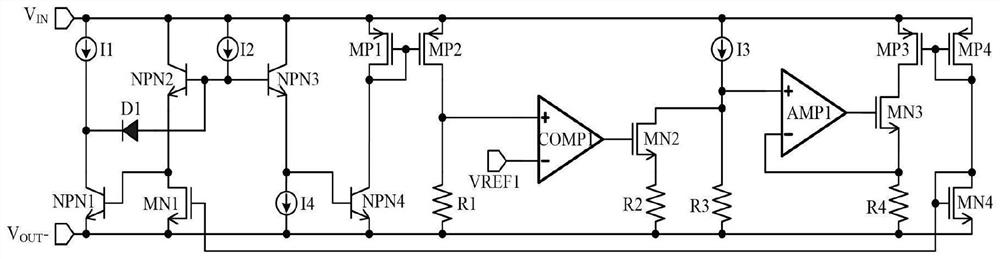
[0032] The present invention provides a frequency adjustment circuit suitable for buck-boost converters, the structure of which is as follows figure 2 As shown, it includes NMOS transistors MN1~MN4, PMOS transistors MP1~MP4, transistors NPN1~NPN4, resistors R1~R4, diodes D1, current sources I1~I4, operational amplifiers AMP1 and comparator COMP1; among them, the drain terminal of NMOS transistor MN1 Connect to the base of the triode NPN1, the gate terminal to the gate terminal of the NMOS tube MN4, and the source terminal to the output terminal V OUT -; The NMOS transistor MN2 drain is connected to the first terminal of the resistor R3, the gate terminal is connected to the output terminal of the comparator COMP1, and the source terminal is connected to the first terminal of the second resistor R2; the drain terminal of the NMOS transistor MN3 is connected to the drain terminal of the PMOS transistor MP3, and the gate terminal is connected to the operation The output terminal...


PUM


Abstract

The invention discloses a frequency adjustment circuit suitable for a buck-boost converter, which belongs to the technical field of electronic analog circuits. The frequency adjustment circuit suitable for buck-boost converters includes NMOS transistors MN1-MN4, PMOS transistors MP1-MP4, triodes NPN1-NPN4, resistors R1-R4, diode D1, current sources I1-I4, operational amplifiers AMP1 and comparison device COMP1. The circuit of the present invention is aimed at the application occasions where the input has instantaneous peaks, and it is not necessary to set the operating frequency of the chip too low in order to increase the conduction time of the power tube, so as to meet the current detection delay requirement for the minimum conduction time of the power tube; thereby avoiding large-sized peripheral devices The use of, and ultimately reduce the design cost.

Description

technical field [0001] The invention relates to the technical field of electronic analog circuits, in particular to a frequency adjustment circuit suitable for buck-boost converters. Background technique [0002] In the power switch control circuit, the buck-boost converter is widely used because of its simple circuit structure, high efficiency, easy control, and arbitrary combination of input and output voltages. Traditional buck-boost converter circuit architecture such as figure 1 shown. PWM is a control logic level, which controls the power transistor MN1 to be turned on and off periodically. D1 is a reverse freewheeling diode. When MN1 is turned on, D1 is turned off, and the external input V IN Charges the inductor L1. When MN1 is off, D1 is on and the reverse freewheeling flow is from the output filter capacitor C OUT draws current on, so the final output V OUT - for negative pressure. [0003] Usually, in order to improve the dynamic response performance of th...

Claims


Application Information

Patent Timeline
Patent Type & Authority Patents(China)
IPC IPC(8): H02M3/158
CPCH02M3/158H02M1/0003
Inventor 奚冬杰徐晴昊李现坤
Owner 58TH RES INST OF CETC
Why Eureka
Try Eureka