[0021] In order to make the objectives, features, and advantages of the present invention more obvious and understandable, the technical solutions in the embodiments of the present invention will be described clearly and completely with reference to the accompanying drawings in the embodiments of the present invention. Obviously, the following The described embodiments are only a part of the embodiments of the present invention, rather than all the embodiments. Based on the embodiments of the present invention, all other embodiments obtained by those of ordinary skill in the art without creative work shall fall within the protection scope of the present invention.
[0022] The technical solutions of the present invention will be further described below in conjunction with the drawings and specific implementations.
[0023] In the description of the present invention, it should be understood that the directions or positional relationships indicated by the terms "upper", "lower", "top", "bottom", "inner", and "outer" are based on the drawings shown The orientation or positional relationship is only for the convenience of describing the present invention and simplifying the description, rather than indicating or implying that the pointed device or element must have a specific orientation, be constructed and operated in a specific orientation, and therefore cannot be understood as a limitation of the present invention.
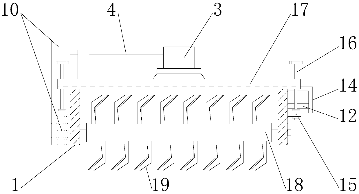
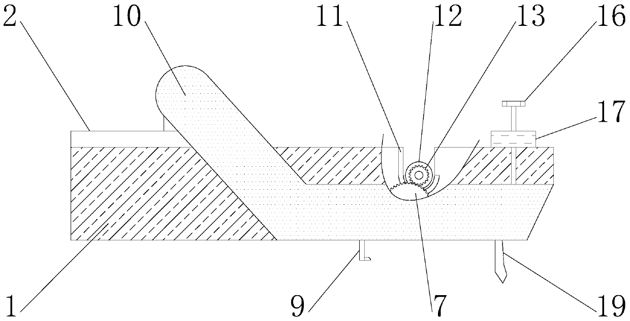
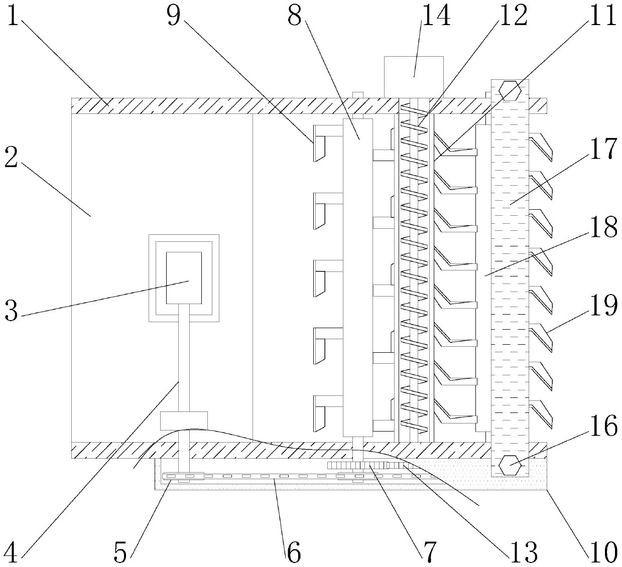
[0024] See Figure 1-3 As shown, a new multi-purpose rotary cultivator includes a top plate 2, a transmission mechanism, and a conveying mechanism installed on the top of the support 1;
[0025] The transmission mechanism includes an engine 3, an output shaft 4 and a sprocket 5. The engine 3 is fixedly connected to the middle of the top plate 2, the output end of the engine 3 is fixedly connected to the output shaft 4, and the end of the output shaft 4 is fixedly connected with a chain Wheel 5, the sprocket wheels 5 are connected in transmission through a chain 6, one of the sprocket wheels 5 is fixedly connected to the first gear 7, and the first gear 7 is fixedly connected coaxially with the end of the first knife roller 8, and The first blades 9 are evenly distributed on the surface of a runner for cutting weeds to avoid long weeds entangled on the blades;
[0026] The conveying mechanism includes a housing 10, a conveying plate 11, and a conveying roller 12. The housing 10 is fixedly connected to the side wall of the bracket 1, and the brackets 1 are fixedly connected by a conveying plate 11, and the conveying is located inside the conveying plate 11. The roller 12 is rotatably connected with the middle part of the bracket 1 and the fixed plate 14, and the other end of the conveying roller 12 is fixedly connected with the second gear 13. The outer wall of the bracket 1 is fixedly connected with the supporting plate 15, the supporting plate 15 and the housing 10 are rotatably connected with the end of the bolt 16 and the bolt 16 is rotatably connected with the baffle 17 for further crushing of the soil block.
[0027] The number of the brackets 1 is two, and the two brackets 1 are respectively located on both sides of the top plate 2, and one of the brackets 1 is fixedly installed with a casing 10, and three sprockets 5 are arranged between the casing 10 and the bracket 1, and The three sprockets 5 are all connected by a chain 6 to facilitate the rotation of the first knife roller 8 and the second knife roller 18, and facilitate the reclamation of the land; the ends of the output shaft 4 and the first knife roller 8 extend to Inside the housing 10, the end of the output shaft 4 and the first knife roller 8 are both fixedly connected to the sprocket 5, and the other sprocket 5 is fixedly connected to the end of the second knife roller 18, and the second knife roller The second blades 19 are evenly distributed on the surface of 18, and the second knife roller 18 is rotatably connected with the support 1 Used for the rotation of the second knife roller 18 to facilitate land reclamation; the conveying plate 11 has a U-shaped cross section, the conveying plate 11 is located between the brackets 1, and the conveying plate 11 is provided with a conveying pipe inside, and An opening with a U-shaped structure is opened at the connection between the conveying plate 11 and one of the brackets 1, which is used for the transportation of soil blocks and facilitates the cleaning of excess soil blocks; the first gear 7 and the second gear at the end of the first knife roller 8 13 are meshed and connected, the first blade 9 on the surface of the first knife roller 8 has an L-shaped structure, and there is a corresponding conveying plate 11 between the first knife roller 8 and the second knife roller 18 to facilitate the first blade 9 The rotation of the baffle 17 facilitates the cutting of weeds; the baffle 17 is located between the two brackets 1, the bottom end of the baffle 17 corresponds to a second knife roller 18, and two ends of the baffle 17 are respectively provided with two A bolt 16 facilitates the adjustment of the height of the baffle 17 and facilitates the adjustment of the conveying volume according to the needs when cleaning the soil.
[0028] When the present invention is in use, when the output shaft 4 is driven to rotate by the work of the engine 3, the output shaft 4 drives the sprocket 5 at its end to rotate, and the transmission of the chain 6 drives the three sprockets 5 to rotate simultaneously, thereby driving the first knife The roller 8 and the second knife roller 18 move at the same time. When the first knife roller 8 rotates, the first blade 9 is driven to rotate, thereby cutting the long weeds on the ground, and avoiding the weeds entangled on the blades, which will reduce the reclamation effect and damage the blades. The problem is conducive to the cultivation of rotary tillers in different environments, and is conducive to the multi-purpose use of rotary tillers;
[0029] When the second knife roller 18 rotates, it drives the second blade 19 to rotate at the same time to reclaim the land. The second blade 19 breaks the soil block and carries part of the soil block to collide with the baffle 17, thereby further reducing the size of the soil block. Make the soil more complete, and at the same time, some soil blocks collide with the baffle 17 and fall into the conveying plate 11. When the sprocket 5 drives the first gear 7 to rotate, the first gear 7 drives the second gear 13 to rotate at the same time, making the second gear 13 drives the conveying roller 12 to rotate inside the conveying plate 11. When the conveying roller 12 rotates between the support 1 and the fixed plate 14, the soil blocks are transported and cleaned from the side of the support 1, which is convenient for cleaning the excess soil blocks. When adjustment is required When cleaning the amount of soil block, by turning the bolt 16 so that the bolt 16 rotates on the top of the support plate 15 and the shell 10, the baffle 17 is driven to move vertically, and the amount of collision between the soil block and the baffle 17 during reclamation is controlled. It realizes the adjustment of the amount of soil blocks entering the inside of the conveying plate 11, which is convenient for use when the ridge height is reduced, and the amount of soil block cleaning can also be adjusted according to the needs of the ridge height, which is convenient for operation and is beneficial to the multi-purpose use of the rotary tiller.
[0030] For those skilled in the art, it is obvious that the present invention is not limited to the details of the foregoing exemplary embodiments, and the present invention can be implemented in other specific forms without departing from the spirit or basic characteristics of the present invention. Therefore, from any point of view, the embodiments should be regarded as exemplary and non-limiting. The scope of the present invention is defined by the appended claims rather than the foregoing description, and therefore it is intended to fall within the claims. All changes within the meaning and scope of the same requirements are included in the present invention. Any reference signs in the claims should not be regarded as limiting the claims involved.
[0031] As mentioned above, the above embodiments are only used to illustrate the technical solutions of the present invention, but not to limit them; although the present invention has been described in detail with reference to the foregoing embodiments, those of ordinary skill in the art should understand that: The technical solutions recorded in the embodiments are modified, or some of the technical features are equivalently replaced; these modifications or replacements do not cause the essence of the corresponding technical solutions to deviate from the spirit and scope of the technical solutions of the embodiments of the present invention.