Gas-liquid mixing device

A gas-liquid mixing and mixing chamber technology, which is applied in the fields of hydrocarbon oil cracking, petroleum industry, chemical instruments and methods, etc. Thermal efficiency, saving investment, easy installation and disassembly

Pending Publication Date: 2020-08-21
CHINA PETROLEUM & CHEM CORP +2
View PDF1 Cites 0 Cited by
  • Summary
  • Abstract
  • Description
  • Claims
  • Application Information

AI Technical Summary

Problems solved by technology

[0009] In order to solve the technical problems existing in the prior art that the gas-liquid two-phase fluid is difficult to distribute evenly in the cataly

Method used


Image

  • Gas-liquid mixing device
  • Gas-liquid mixing device
  • Gas-liquid mixing device

Examples


Embodiment Construction

[0036] The present invention will be further described below in conjunction with the accompanying drawings.

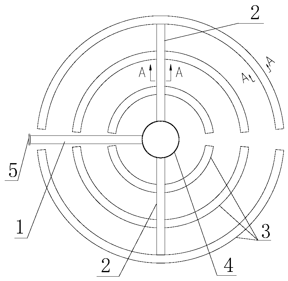
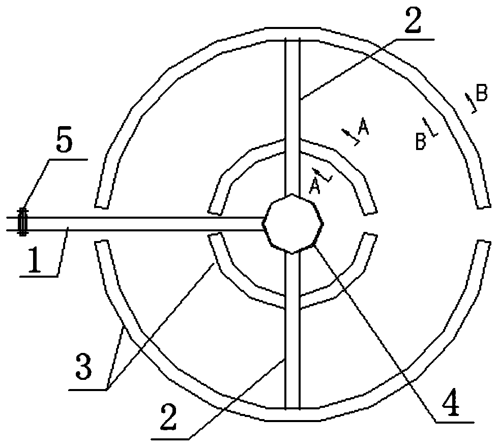
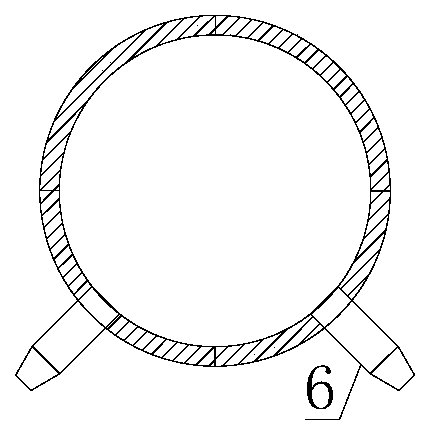
[0037] Such as Figure 1~5 As shown, the cold hydrogen distributor of the present invention includes an inlet pipe 1, a distribution ring pipe 3, a distribution straight pipe 2, a nozzle 6 and a mixing chamber 4, and the inlet pipe 1, the distribution ring pipe 3, the distribution straight pipe 2 and the mixing chamber 4 are all Located in the same plane; the distribution ring pipe 3 is in the shape of a semicircular arc with both ends closed, and is distributed concentrically with the mixing chamber 4 as the center; the mixing chamber 4 is a cylindrical body with an open upper end and a closed bottom; the distribution straight pipe 2 and the distribution The ring pipe 3 intersects and runs through, one end of the distribution straight pipe 2 communicates with the side wall of the mixing chamber 4, and the other end communicates with the distribution ring pipe 3; the d...


PUM


Abstract

The invention discloses a gas-liquid mixing device. The device comprises a shell, and a catalyst grid, a collecting disc, a cold hydrogen distributor, a bubble cap, a coarse distribution disc, gas-liquid distributors, a distribution disc and a redistribution disc which are arranged in the shell from top to bottom, wherein the cold hydrogen distributor is fixedly connected with a central hole of the collecting disc through an opening in the upper end of a mixing chamber and mainly comprises a gas inlet pipe, distribution ring pipes, distribution straight pipes, a nozzle and the mixing chamber,the distribution ring pipes are concentrically distributed by taking the mixing chamber as the center, the distribution straight pipes and the distribution ring pipes are crossed and communicated, andthe distribution straight pipes and the gas inlet pipe are communicated with the side wall of the mixing chamber. The device is simple and compact in structure and suitable for being used between catalyst bed layers of a large-diameter down-flow reactor; and cold hydrogen can be more uniformly distributed on the total cross section of the reactor and can be fully mixed with reaction oil gas, so that uniform mass transfer and heat transfer are guaranteed, and the heat transfer efficiency of a medium in the reactor is improved.

Description

technical field [0001] The invention belongs to the field of petroleum processing, and relates to a gas-liquid mixing and distribution device for a hydrogenation reactor, in particular to a gas-liquid mixing device. Background technique [0002] Due to the exothermic reaction of gas, liquid and solid in the hydrogenation process, in order to make the reaction feed (gas and liquid two phases) and the catalyst (solid phase) fully, uniformly and effectively contact, the hydrogenation reactor is generally designed There are multiple catalyst beds, a distribution plate is set on the top of each bed, and a temperature control structure (cold hydrogen box) is installed between the two beds to ensure the safe and stable production and extension of the hydrogenation unit Catalyst service life. [0003] The hydrogenation reaction of hydrocarbons is an exothermic reaction. For a multi-bed hydrogenation reactor, the temperature of oil gas and hydrogen will rise after the reaction of th...

Claims


Application Information

Patent Timeline
IPC IPC(8): B01J8/04C10G45/00C10G47/00C10G49/00
CPCB01J8/04B01J8/0278B01J8/0285B01J8/0292C10G45/00C10G47/00C10G49/00
Inventor 张国信李双权李群生苏月丁同银赵璐
Owner CHINA PETROLEUM & CHEM CORP
Why Eureka
Try Eureka