Mechanism for securing a digital lock from unauthorized use

A digital lock and lock body technology, applied in the field of digital locks, to achieve the effects of easy implementation, reliable energy consumption, and small size

Active Publication Date: 2020-08-21
ILOQ OY
View PDF12 Cites 0 Cited by
  • Summary
  • Abstract
  • Description
  • Claims
  • Application Information

AI Technical Summary

Problems solved by technology

[0013] However, prior art locks are insufficient in providing a low or zero energy security mechanism to isolate the lock in the event of an attempted unauthorized use

Method used


Image

  • Mechanism for securing a digital lock from unauthorized use
  • Mechanism for securing a digital lock from unauthorized use
  • Mechanism for securing a digital lock from unauthorized use

Examples


Embodiment approach 10

[0082] Any feature of embodiment 10 can be readily combined with other embodiments 20, 30, 40, 50, 51, 60, 70, 80, 90, 91, 92, 93, 94, 95, 96, 97, 98 according to the invention , 99, 101, 102, 103, 104, 105, 106, 107, 108, 109, 116, 111, 112, 113, 114, 115, 117, 118, 119, 121, 122, 123, 124 and / or 125 Any combination or permutation of them.

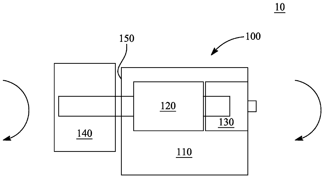
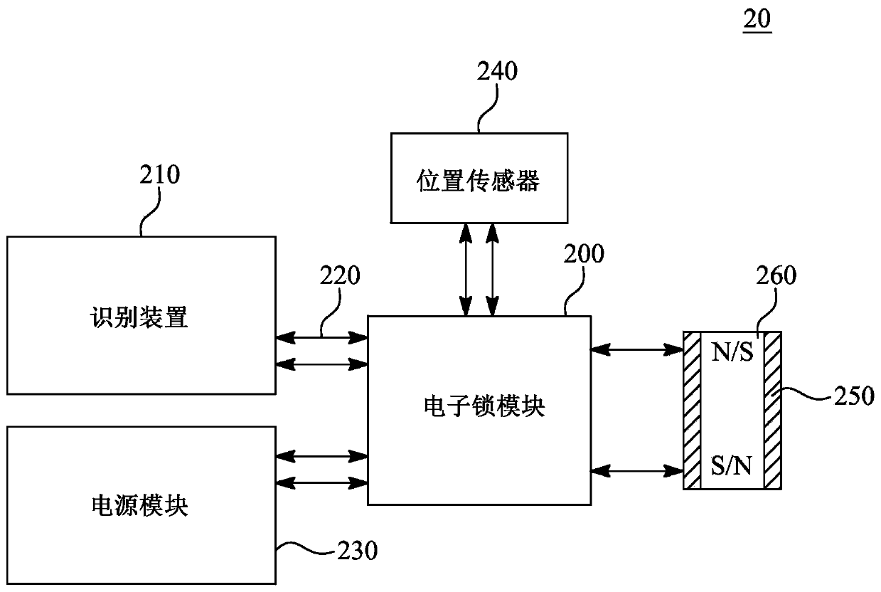
[0083] figure 2 Embodiment 20 of a digital lock 100 according to the invention is shown in a block diagram. The digital lock 100 also includes an electronic lock module 200 connected to the identification device 210 via the communication bus 220 . The communication bus 220 is configured to transmit data between the identification device 210 and the electronic lock module 200 .

[0084] The identification device 210 is configured to identify the user via any of the following: a key tag, a fingerprint, a magnetic strip and / or a near field communication (NFC) device. The identification means 210 can identify the user and allow access to...

Embodiment approach 20

[0089] Any feature of embodiment 20 may be readily combined with other embodiments 10, 30, 40, 50, 51, 60, 70, 80, 90, 91, 92, 93, 94, 95, 96, 97, 98 according to the invention , 99, 101, 102, 103, 104, 105, 106, 107, 108, 109, 116, 111, 112, 113, 114, 115, 117, 118, 119, 121, 122, 123, 124 and / or 125 Any combination or permutation of them.

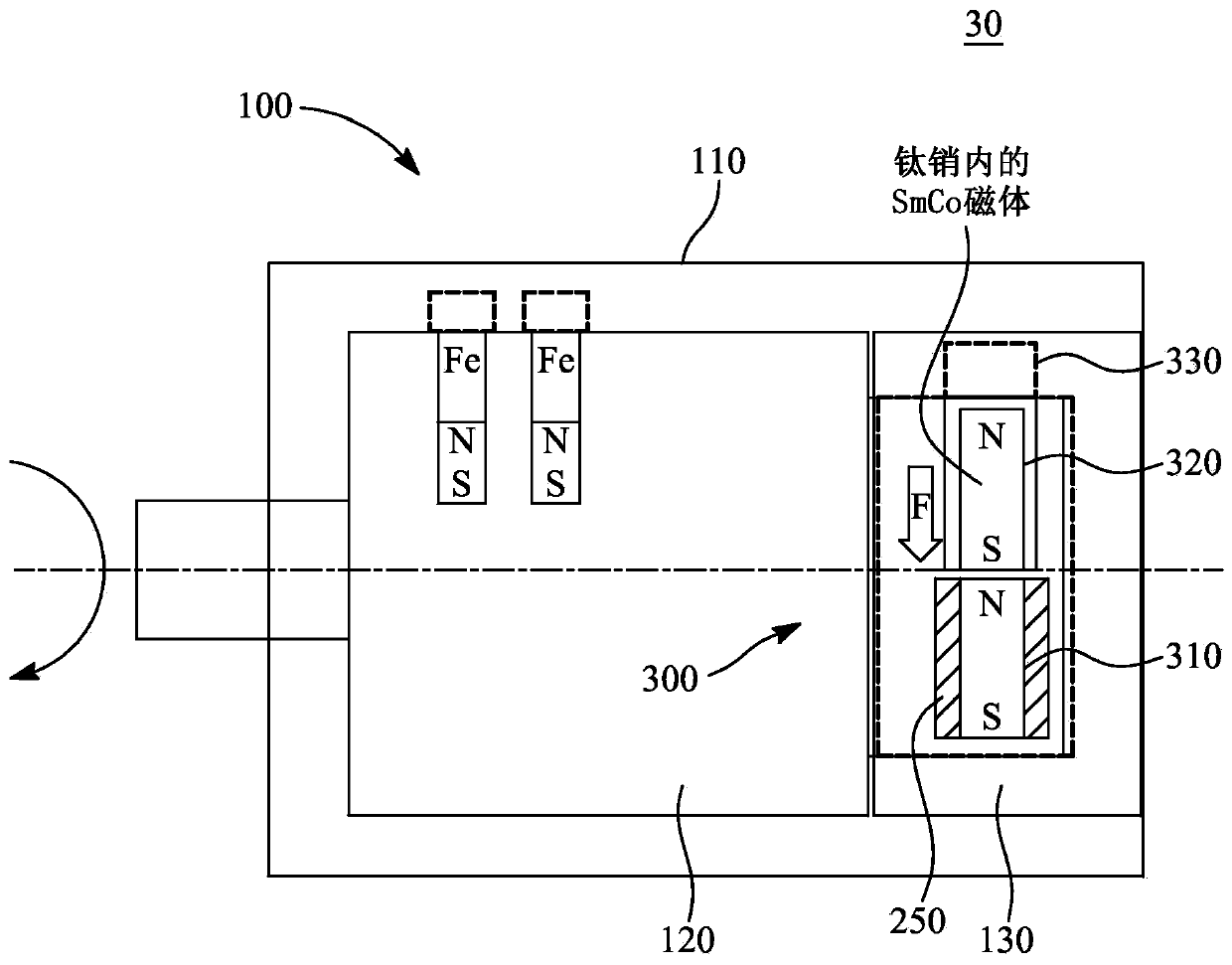
[0090] image 3 An embodiment 30 of a digital lock 100 according to the invention is shown in a block diagram in a locked state 300 . The digital lock 100 includes a semi-hard magnet 310 and a hard magnet 320 configured to open or close the digital lock 100 . Semi-hard magnet 310 is placed adjacent to hard magnet 320 . Additionally, a semi-hard magnet 310 is located within the magnetizing coil 250 . In this embodiment, the semi-hard magnet 310 is made of Alnico, and the hard magnet 320 is made of SmCo. In particular, the semi-hard magnet 310 is made of an iron alloy composed of aluminum (Al), nickel (Ni), and cobalt (Co) in addition ...

Embodiment approach 30

[0095] Any feature of embodiment 30 can be readily combined with other embodiments 10, 20, 40, 50, 51, 60, 70, 80, 90, 91, 92, 93, 94, 95, 96, 97, 98 according to the invention , 99, 101, 102, 103, 104, 105, 106, 107, 108, 109, 116, 111, 112, 113, 114, 115, 117, 118, 119, 121, 122, 123, 124 and / or 125 Any combination or permutation of them.

[0096] Figure 4 An embodiment 40 of a digital lock 100 according to the invention is shown in a block diagram in an openable state 400 . as before about image 3 As depicted, the digital lock 100 includes a semi-hard magnet 310 and a hard magnet 320 configured to open or close the digital lock 100 . The semi-hard magnet 310 is placed adjacent to the hard magnet 320 . Additionally, a semi-hard magnet 310 is located within the magnetizing coil 250 . When the polarity of the half-hard magnet 310 is changed by the magnetizing coil 250 , the half-hard magnet 310 is configured to push or pull the hard magnet 320 to open or close the digit...


PUM


Abstract

The invention provides a digital lock (1003, 1004) including at least two magnets. One magnet is a semi-hard magnet (2730) and the other magnet is a hard magnet (2720). The hard magnet (2720) is configured to move to close the digital lock (1003, 1004) in the event of malicious attack, blocking the intruder thereby the magnets (2720, 2730) acting as a blocking pin (2700), and the mechanical and / orelectromagnetic energy of the attack is configured to move the hard magnet (2720) to seal the digital lock (1003, 1004) from the intruder.

Description

technical field [0001] The present invention relates generally to digital locks for doors, and more particularly to mechanisms for preventing unauthorized use of digital locks. Background technique [0002] Electromechanical locks have replaced traditional mechanical locks. Electromechanical locks are locking devices operated by magnetic force or electric current. Electromechanical locks are sometimes self-contained, with electronic control components mounted directly to the lock. Additionally, electromechanical locks use magnets, solenoids, or electric motors to actuate the lock by supplying power or de-energizing it. The electromechanical lock is configured to operate between a locked state and an unlocked state. Typically, in the locked state of the electromechanical lock, power is continuously supplied to the electromagnet to maintain the electromechanical lock in the locked state. In addition, electromechanical locks consume a lot of energy due to the use of electri...

Claims


Application Information

Patent Timeline
Patent Type & Authority Applications(China)
IPC IPC(8): E05B47/00E05B47/02
CPCG07C9/00174G07C9/00563E05B47/063E05B47/0038E05B47/0041E05B2047/0094E05B47/0006E05B2047/0092E05B17/2092E05B27/0071G07C9/00944G07C2009/00634E05B47/0649E05B47/0673E05B47/0692E05B2047/0028E05B2047/0036E05B2047/0057E05B2047/0066E05B2047/0075E05B2047/0079E05B47/0005G07C9/00698G07C9/00722G07C9/00817G07C9/00896
Inventor 米卡·普卡里
Owner ILOQ OY
Why Eureka
Try Eureka