Accurate alignment method for rotary parts

A kind of parts and precise technology, which is applied in the field of accurate alignment of rotary parts, can solve the problems of low alignment accuracy, increased processing cost, and low processing efficiency, and achieve low alignment accuracy, reduce production costs, and reduce labor intensity. Effect

Active Publication Date: 2020-08-25
DALIAN UNIV OF TECH
View PDF14 Cites 7 Cited by
  • Summary
  • Abstract
  • Description
  • Claims
  • Application Information

AI Technical Summary

Problems solved by technology

[0004] In ultra-precision turning or ultra-precision grinding, when the parts are clamped, the process of ensuring that the center line of rotation of the part and the center line of the machine tool spindle are coaxial is called alignment. The important process of process machining allowance control is mainly manifested in two aspects: first, for single-sided machining of rotary parts, the alignment accuracy is low, that is, the center line of the part and the actual spindle are relatively eccentric, and the parts revolve around the machine tool spindle. The eccentric movement of the center line of rotation leads to uneven machining allowances, changes in the depth of cut of the tool during the machining process, and fluctuations in the cutting force lead to unstable machining processes, which can easily cause tool breakage and poor surface quality of the parts. Low precision, large eccentricity between the center line of rotation of the part and the actual center line of rotation of the spindle, more machining allowance must be reserved in the previous process to ensure the control of dimensional accuracy during subsequent part processing, which will inevitably lead to low processing efficiency and increased processing costs ; Second, especially for double-sided machining of rotary parts, secondary clamping and positioning are required for the processing of inner and outer surfaces. Different axes, even if the theoretical contour accuracy of the inner and outer surfaces is very high, which can meet the requirements, but due to the coaxiality deviation of the center line of rotation of the inner and outer surfaces, it will inevitably cause a large error in the wall thickness of the parts, which is difficult to meet the high-precision processing requirements of the parts
At present, for single-sided machining of ordinary parts, precision / ultra-precision machining is not required, and the machining efficiency is high. Usually, the operator uses a dial indicator or a dial gauge to detect the radial runout of the part, and then uses copper rods, Soft rods such as aluminum rods, rubber or plastics or hammers hit the outer circle of the parts to make the center of the parts coaxial with the center of the machine tool spindle. This method is fast and convenient, but the alignment accuracy is low, usually above 10 microns, which is useful for some Parts with higher machining accuracy requirements can be aligned repeatedly by highly skilled workers, and alignment accuracy close to the micron level can be obtained, and by appropriately increasing the machining allowance of the parts, it can meet the requirements of rotary parts that only need to be processed on one side. requirements, but it is difficult and time-consuming
[0005] Even so, however, when both the inner and outer surfaces of a part need to be processed to ensure the inner and outer surface contour accuracy, dimensional accuracy and wall thickness error of the part at the same time, the alignment error directly determines the machining wall thickness error of this type of part, and it is impossible to increase the machining allowance of the part Reduce or eliminate, at this time, the alignment accuracy has become a key technical bottleneck that restricts the further improvement of the machining accuracy of parts. It is difficult to achieve sub-micron alignment accuracy in ultra-precision machining by relying on operating technicians

Method used


Image

  • Accurate alignment method for rotary parts
  • Accurate alignment method for rotary parts

Examples


Embodiment Construction

[0035] The present invention will be described in detail below in conjunction with the accompanying drawings.

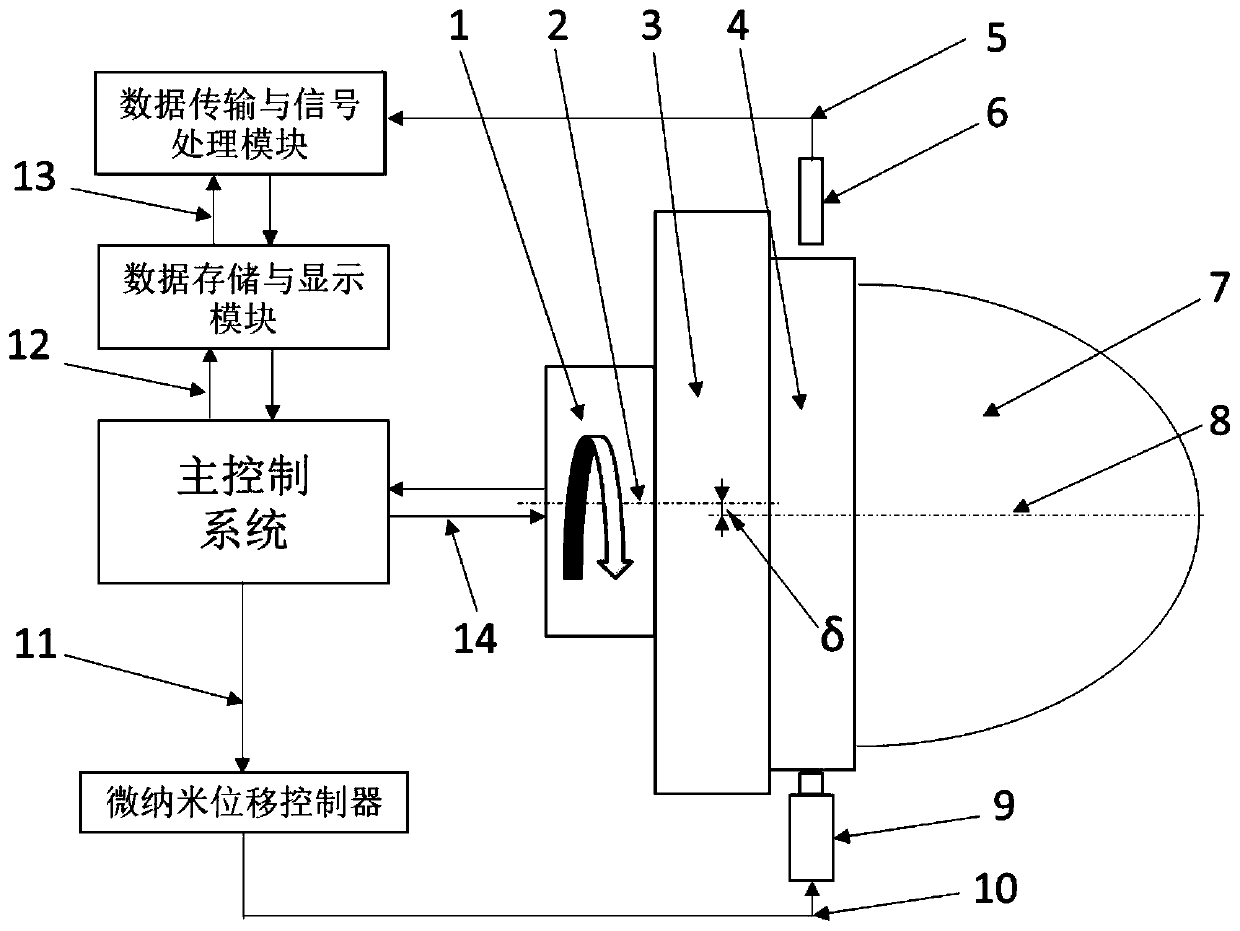
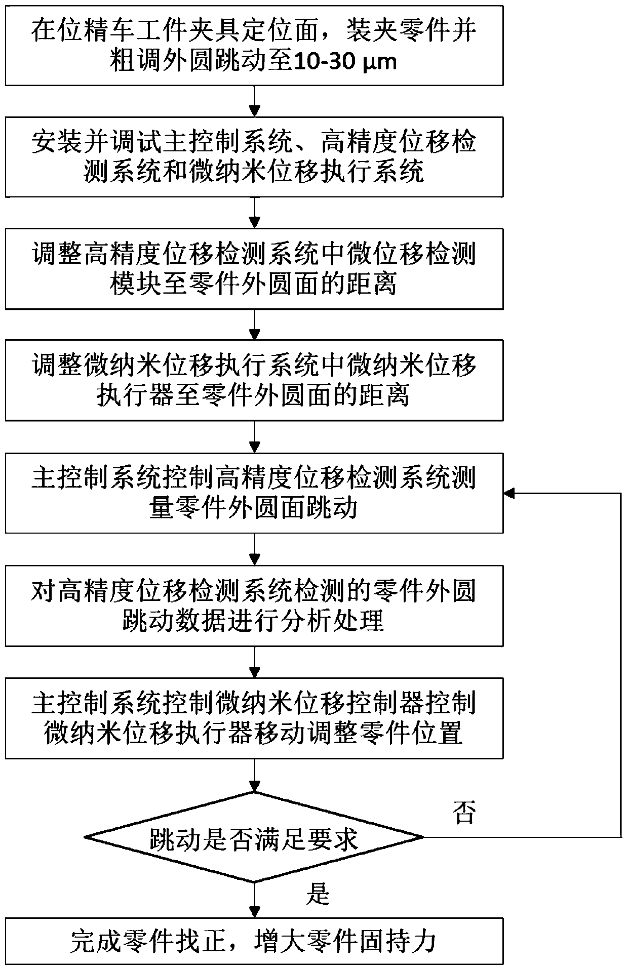
[0036] Such as figure 1 and figure 2 As shown, the precise alignment method of rotary parts includes the following steps:

[0037] A. Install the rotary workpiece fixture 3 on the machine tool spindle 1, position the rotary workpiece fixture 3 on the in-position finish car, and attach the flange 4 of the rotary curved surface part 7 to the rotary workpiece fixture 3 positioning installation surface, And adjust the holding force so that the rotary curved surface part 7 can be pushed but does not automatically slide down, install the rotary curved surface part 7 and roughly adjust the runout of the outer circle of the flange 4 to 10-30 μm.

[0038] B. Install and debug the main control system, high-precision displacement detection system and micro-nano displacement execution system;

[0039] Install and fix the micro-displacement detection module 6 near the flange ...


PUM


Abstract

The invention relates to an accurate alignment method for rotary parts, and belongs to the field of precision ultra-precision machining. The accurate alignment method for the rotary parts comprises the following steps that 1), in-situ finish turning is carried out on a positioning mounting surface of a rotary workpiece clamp, the parts are attached to the positioning mounting surface of the rotaryworkpiece clamp, the holding force is reduced until the parts can be pushed but do not automatically slide off; a main control system, a high-precision displacement detection system and a micro-nanodisplacement execution system are installed and debugged; 2), the distance from a micro-displacement detection module in the high-precision displacement detection system to the outer circle surface ofa return part and the distance from a micro-nano displacement actuator in the micro-nano displacement execution system to the outer circle surface of the return part are adjusted; 3), the main control system controls the high-precision displacement detection system to detect the runout of the outer circle surfaces of the parts, and controls the micro-nano displacement actuator to move and push the parts to move according to the runout detection result of the outer circle surfaces of the parts; and 4), the step 3) is repeated until the jerk value of the parts is less than or equal to the maximum theoretical calculation jerk value, and alignment is completed. According to the accurate alignment method for the rotary parts, the production cost can be reduced, the alignment precision can reach a submicron level or even a nanoscale level, and the repeatability of the alignment precision is good.

Description

technical field [0001] The invention belongs to the field of precision ultra-precision machining, and relates to a method for accurately aligning rotary parts. Background technique [0002] Rotary parts, such as: rings, shafts, bushings, spherical or aspherical parts, housings, etc., are widely used in the fields of automobiles, medical, electronics, precision instruments, aerospace, military and precision physics experiments. In order to meet the application requirements for high performance and high reliability in different fields, extremely stringent requirements are put forward for the processing accuracy of parts. The processing accuracy of key parts needs to reach the precision or ultra-precision level, that is, the dimensional accuracy is required to reach micron or even sub- Micron level, surface roughness reaches nanometer level. [0003] As the key components in industrial applications, high-precision rotary parts are mainly processed by ultra-precision turning, u...

Claims


Application Information

Patent Timeline
Patent Type & Authority Applications(China)
IPC IPC(8): B23Q3/12B23Q15/22
CPCB23Q3/12B23Q15/22
Inventor 康仁科焦振华郭江董志刚
Owner DALIAN UNIV OF TECH
Why Eureka
Try Eureka