
Pen point feeding system

A technology of pen head and conveying mechanism, which is applied in the direction of conveyor control devices, conveyor objects, conveyors, etc., can solve the problems of poor rigidity of V-groove belt transmission, easy deformation of V-groove belt, and affecting work efficiency, etc., to achieve material feeding Stable, save time, improve the effect of assembly efficiency

Pending Publication Date: 2020-08-25
扬州威远机械制造有限公司
View PDF0 Cites 3 Cited by
  • Summary
  • Abstract
  • Description
  • Claims
  • Application Information

AI Technical Summary

Problems solved by technology

[0003] Existing technologies such as Figure 7 As shown, the nib coming out of the silo is stored on the V-shaped groove belt 100, and is driven to the end of the feeding device through the belt, and the push rod 101 set aside is stretched in from the outer end face of the V-shaped groove belt, and the nib Push it to the assembly station to assemble with the pen holder. At this time, the push rod in place is in the V-shaped groove belt. The V-groove belt can continue to move forward until the push rod in place is completely retracted from the V-shaped groove belt. The whole process takes a long time. Long, which affects work efficiency, and the V-groove belt transmission rigidity is poor. After a period of use, the V-groove belt is easy to deform, resulting in misalignment with the push rod in place, unstable feeding, and affecting production.

Method used


Image

  • Pen point feeding system
  • Pen point feeding system
  • Pen point feeding system

Examples


Embodiment Construction

[0030] Below in conjunction with accompanying drawing and specific embodiment, further illustrate the present invention, it should be understood that these embodiments are only used to illustrate the present invention and are not intended to limit the scope of the present invention, after having read the present invention, those skilled in the art will understand various Modifications in equivalent forms all fall within the scope defined by the appended claims of this application.

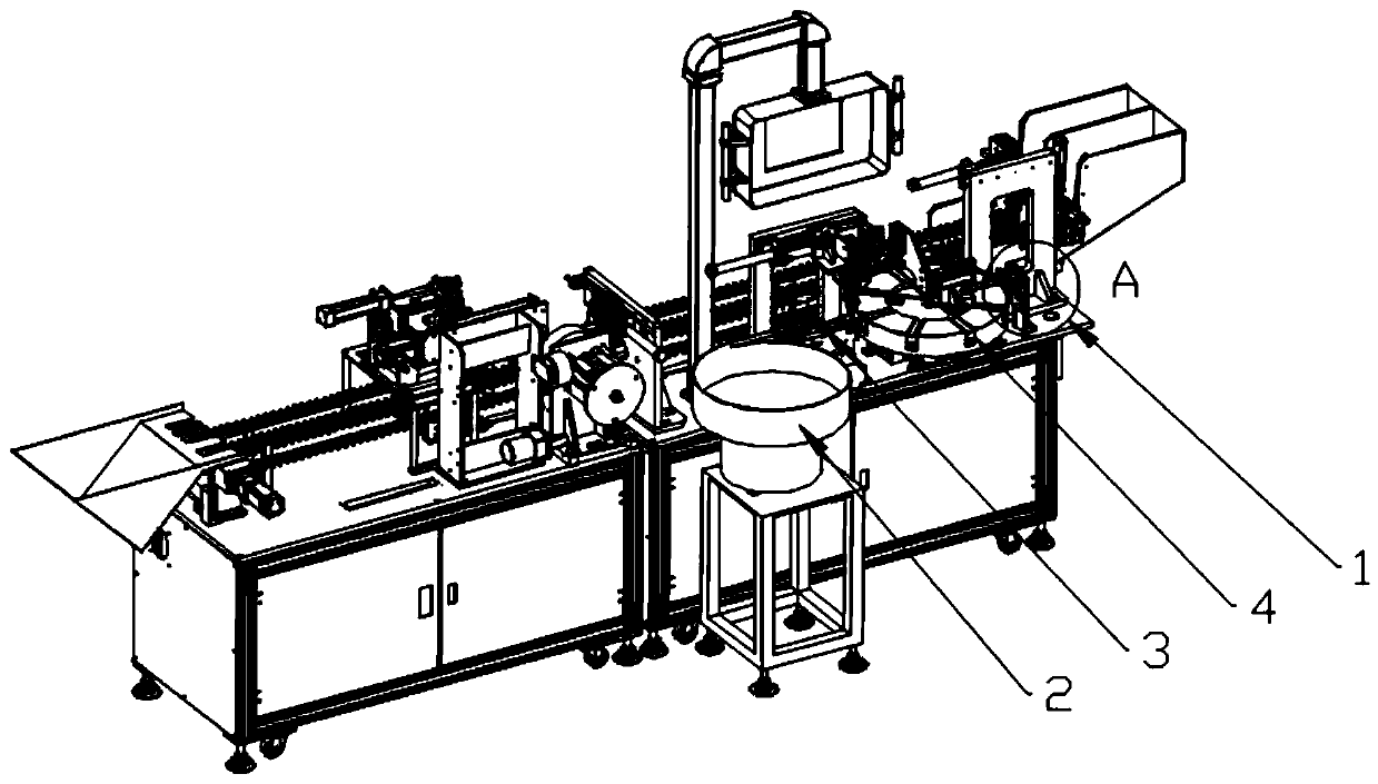
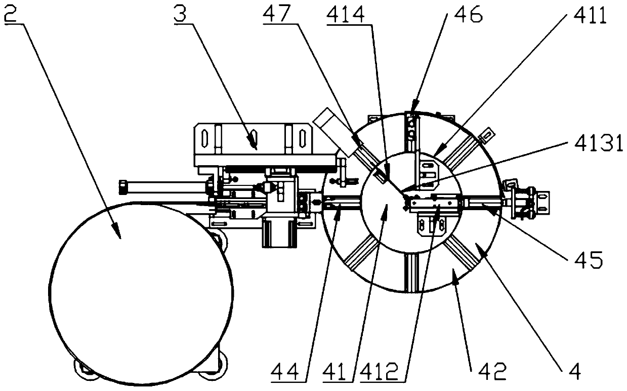
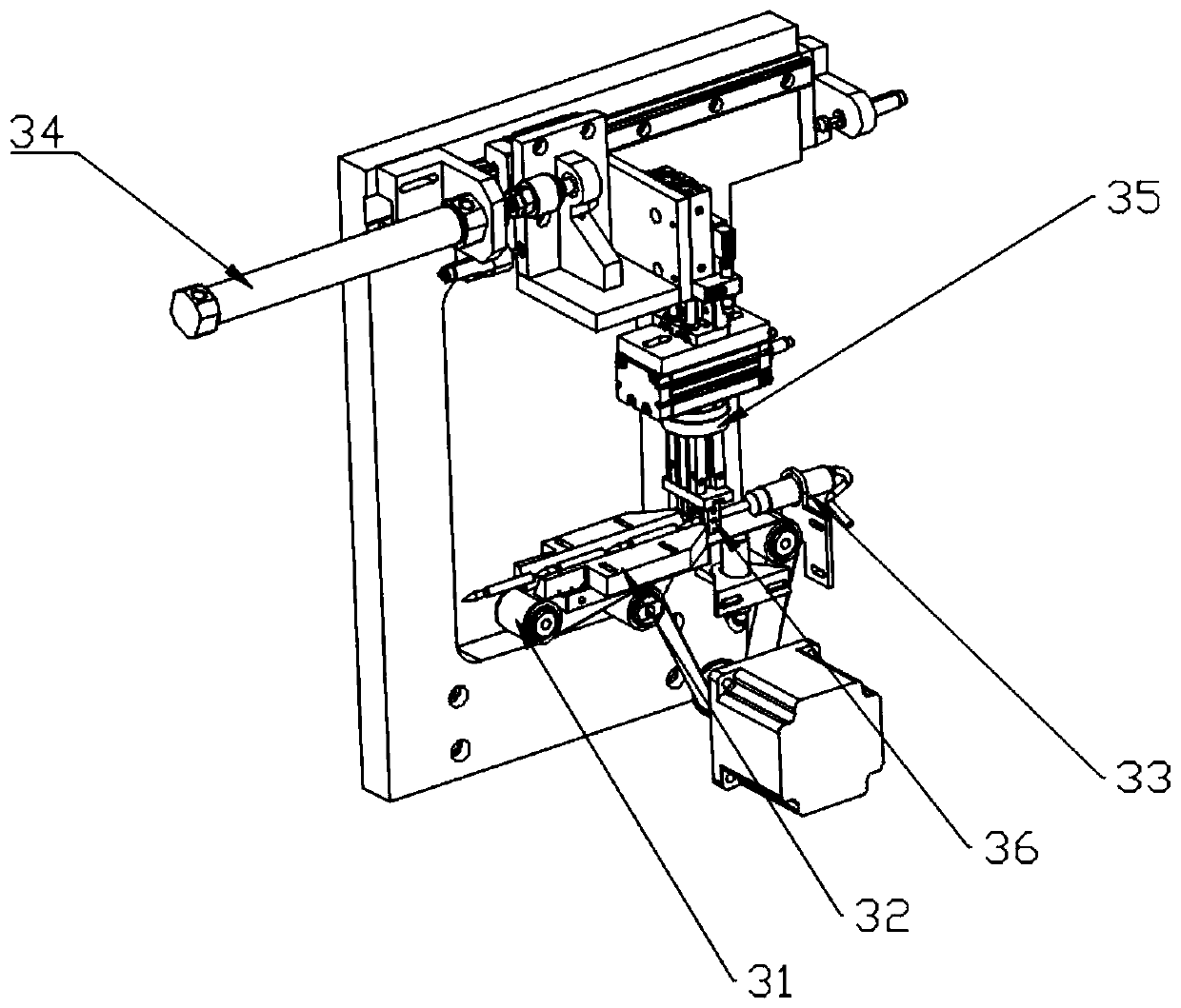
[0031] Such as Figure 1-6As shown, a nib feeding system includes a frame 1, the rack is equipped with a vibrating plate 2 for orienting the nib, the discharge end of the vibrating plate is connected with the secondary conveying mechanism 4 through a primary conveying mechanism 3, and the nib is passed through The primary conveying mechanism is transferred to the secondary conveying mechanism, and the primary conveying mechanism includes a conveyor belt 31 on which the positioning guide groove 32 f...


PUM


Abstract

The invention discloses a pen point feeding system. The pen point feeding system comprises a rack, a vibration disc is installed on the rack, the discharging end of the vibration disc is connected with a second-stage conveying mechanism through a first-stage conveying mechanism, the second-stage conveying mechanism comprises a fixed disc, the outer side of the fixed disc is sleeved with a movabledisc, the movable disc is provided with a driving device, the driving device drives the movable disc to intermittently rotate around the axis in an indexing mode, a plurality of V-shaped supporting plates are arranged on the upper end face of the movable disc at equal intervals, first air cylinders are arranged on the V-shaped supporting plates, a fence fixedly connected with the rack is arrangedon the outer side of the movable disc, an in-place mechanism corresponding to the fence is installed on the fixed disc, a pressing mechanism fixedly connected with the fixed disc is arranged on a station behind the in-place mechanism, the pressing mechanism comprises a sliding block and a second air cylinder driving the sliding block to move up and down, and a pen point is fixed through the downwards-pressed sliding block and the jacked V-shaped supporting plates so as to be used for assembling a pen holder. According to the pen point feeding system, the problems that in the prior art, feedingis unstable, and the assembling efficiency of the pen point and the pen holder is low are solved.

Description

technical field [0001] The invention relates to paintbrush production equipment, in particular to a brush head feeding system. Background technique [0002] The paintbrush includes a nib and a pen barrel. During the mass production of pens, it is necessary to classify the nib and the pen barrel before assembling them. Because the pen holder is long, it can be neatly stacked and placed in the pen holder by the operator in advance; one end of the pen head is a hair bundle, and the other end is a metal sleeve, and the overall size is relatively short, which is not convenient for the operator to arrange in advance. Numerous nibs are poured into the huge nib silo, which must be in a state of disorder. The premise of industrialized assembly is to take out many messy and disordered nibs from the nib bin one by one, and then transport them to the assembly station. [0003] Existing technologies such as Figure 7 As shown, the nib coming out of the silo is stored on the V-shaped gr...

Claims


Application Information

Patent Timeline
Patent Type & Authority Applications(China)
IPC IPC(8): B65G27/00B65G47/14B65G47/24B65G47/248B65G47/82B65G43/08B23P19/00
CPCB23P19/002B65G27/00B65G43/08B65G47/1421B65G47/24B65G47/248B65G47/82B65G2203/042
Inventor 张永林刘彪顾涛
Owner 扬州威远机械制造有限公司
Learn More