A multifunctional brick laying device

A brick laying device and multi-functional technology, applied in the direction of construction and building structure, can solve the problems of human injury, large brick laying truck, consuming workers' physical strength and labor time, etc., to reduce brick damage, reduce spacing, The effect of reducing friction

Active Publication Date: 2021-12-31
乐陵市卓亚新型建材有限公司
View PDF13 Cites 0 Cited by
  • Summary
  • Abstract
  • Description
  • Claims
  • Application Information

AI Technical Summary

Problems solved by technology

[0003] The above are the operation steps of the brick laying process, because in the process of laying bricks, the floor tiles are laid one by one on the mud of the base layer manually, and at the same time, leveling operations are required, which reduces the efficiency of laying bricks. Consume workers' physical strength and labor time
At the same time, squatting for a long time and carrying bricks often cause damage to the human body and affect health
Although there is a kind of brick-laying vehicle for laying the road surface, the build of the brick-laying vehicle is relatively large, so it is not suitable for the family room, and the paving vehicle can only be used for laying the ground and cannot lay wall tiles on the wall.

Method used


Image

  • A multifunctional brick laying device
  • A multifunctional brick laying device
  • A multifunctional brick laying device

Examples


Embodiment 1

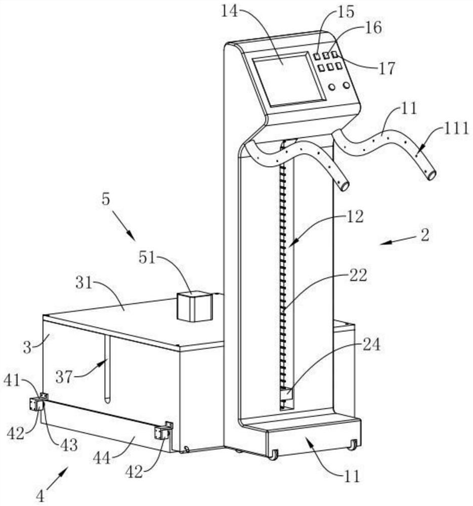
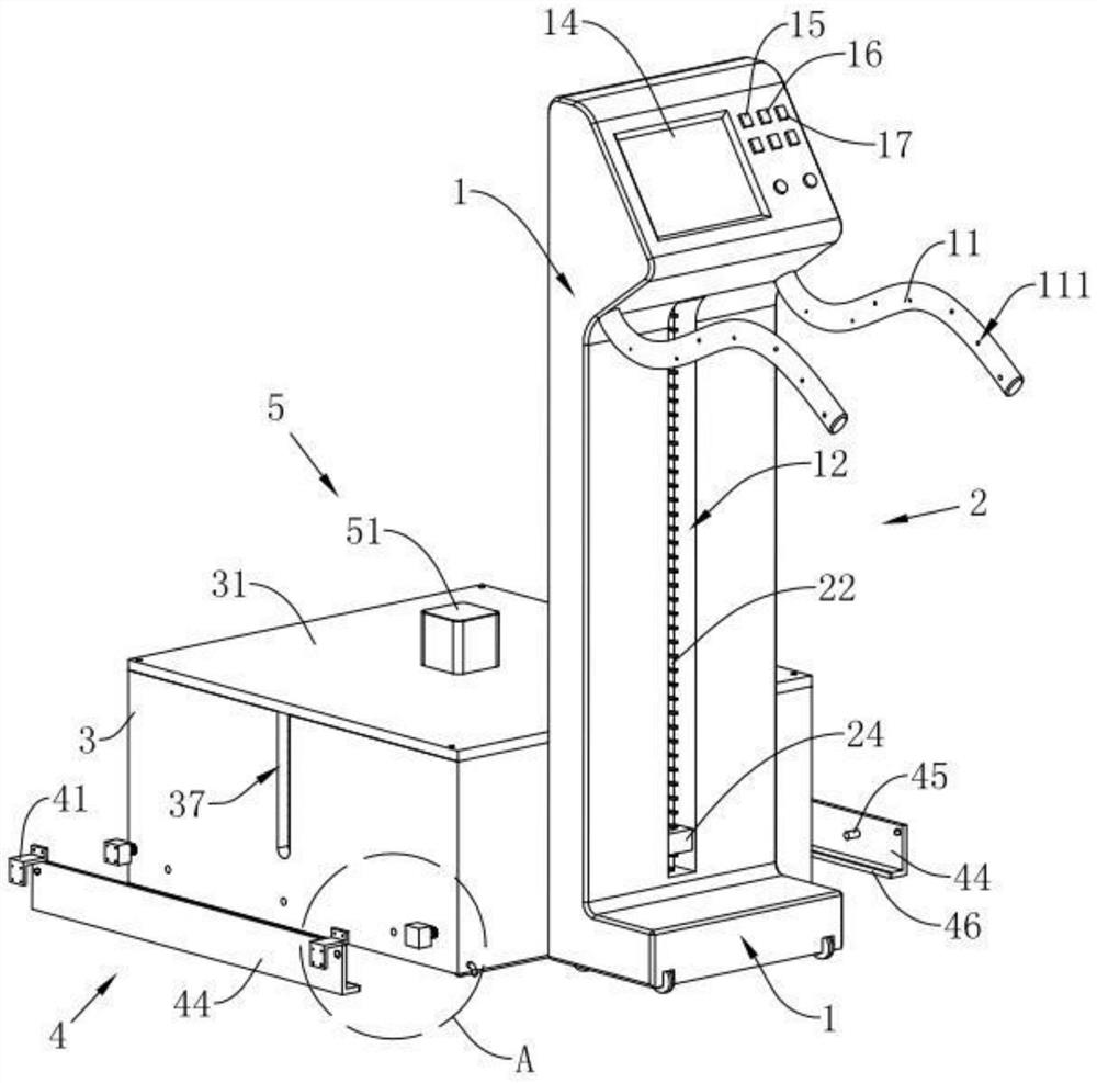
[0032] refer to figure 1 and figure 2The shown multifunctional brick laying device includes a vertical cart 1, which is arranged in an "L" shape, and the pushing end of the vertical cart 1 is fixedly connected with two push handles 11, the push handles The surface of 11 is provided with anti-slip lines 111 that enhance frictional force. The vertical cart 1 is equipped with a lifting assembly 2 away from its pushing end. The lifting assembly 2 lifts along the height direction of the vertical cart 1. A number of brick-laying tubes 3 stacking bricks on each other, the shape of the brick-laying tube 3 and the inner wall of the tube are all arranged in a square shape, and the two opposite sides of the brick-laying tube 3 are connected by a passageway connected to the inside of the brick-laying tube 3. Groove 37, through groove 37 is connected with the barrel mouth of brick-laying tube 3 towards sealing plate 31, the passage of brick-laying tube 3 is set towards the ground or wall...

Embodiment 2

[0056] The difference between embodiment 2 and embodiment 1 is:

[0057] refer to Figure 11 As shown, the pusher 5 includes four guide rods 53 fixedly connected with the seal plate 31 away from the end face of the brick laying cylinder 3, the guide rods 53 are arranged parallel to the plane of the seal plate 31, and the end of the guide rod 53 is fixedly connected to the seal plate 31. Bit block 531, the four guide rods 53 are plugged with the same second motor 54, the driving end of the second motor 54 rotates coaxially and has a thread that penetrates the sealing plate 31 and faces the first lead screw 55 in the brick laying tube 3, the push plate 52 is rotatably connected to the end of the first lead screw 55 away from the second motor 54 , and the two opposite sides of the pushing plate 56 abut against the inner wall of the brick laying cylinder 3 . The vertical cart 1 is provided with a second button 16 on one side of the display screen 14 for controlling the operation ...


PUM


Abstract

The invention discloses a multifunctional brick-laying device, which is characterized in that it comprises a vertical trolley, the vertical trolley is provided with a lifting assembly, the lifting assembly is detachably connected with a brick-laying tube for placing bricks, and a passage for the brick-laying tube Set facing the ground or the wall, one end of the brick laying cylinder along its channel is provided with a limit assembly to limit the bricks from falling out or for the bricks to slide out, and the mouth of the brick laying cylinder at the end away from the limit assembly is detachably connected with a seal The sealing plate at the mouth of the brick-laying cylinder is provided with a pusher for pushing the bricks in the brick-laying cylinder. By adopting the above setting, the pusher is used to push the bricks in the brick laying tube to move the bricks to the ground or the wall and lay the bricks, replacing most of the manual operations, and the overall structure can be used for laying both floor tiles and laying bricks. Under the multifunctional function of wall tiles, the effect of improving people's working comfort is achieved.

Description

technical field [0001] The invention relates to the technical field of brick laying tools, in particular to a multifunctional brick laying device. Background technique [0002] Many families usually lay bricks during decoration. The steps of laying bricks are as follows: 1. Clean up the laitance and ground ash at the base; 2. According to the horizontal standard line and design thickness, pop the surface on the surrounding walls and columns The elevation control line of the first floor; 3. Discharge the position of the bricks on the bottom plate, and pop up the cross control line and the grid line on the base floor; 4. Wet the base layer, and brush a plain cement slurry on the base layer, and lay and stir Uniform dry hard cement mortar; 5. Place the bricks on the previously laid mortar by hand, and level them with a rubber hammer; The surface of the finished floor tiles is watered and cured within one day. [0003] The above are the operation steps of the brick laying proc...

Claims


Application Information

Patent Timeline
Patent Type & Authority Patents(China)
IPC IPC(8): E04F21/18E04F21/22
CPCE04F21/18E04F21/1838E04F21/22
Inventor 古敬青
Owner 乐陵市卓亚新型建材有限公司
Why Eureka
Try Eureka