
IGBT device structure and preparation method thereof

A technology of device structure and junction area, applied in semiconductor/solid-state device manufacturing, semiconductor devices, electrical components, etc., can solve problems such as negative resistance snapback, and achieve the effect of ensuring device withstand voltage, improving insulation, and suppressing the phenomenon of snapback.

Inactive Publication Date: 2020-08-25
潘克学
View PDF0 Cites 2 Cited by
  • Summary
  • Abstract
  • Description
  • Claims
  • Application Information

AI Technical Summary

Problems solved by technology

If the IGBT and the diode can be designed in the same device structure, it will undoubtedly save a lot of cost, and at the same time, the IGBT and FRD will have better matching, but such a structure usually causes the negative resistance snapback phenomenon during turn-on

Method used


Image

  • IGBT device structure and preparation method thereof
  • IGBT device structure and preparation method thereof

Examples


Embodiment Construction

[0028] The following are specific embodiments of the present invention and in conjunction with the accompanying drawings, the technical solutions of the present invention are further described, but the present invention is not limited to these embodiments.

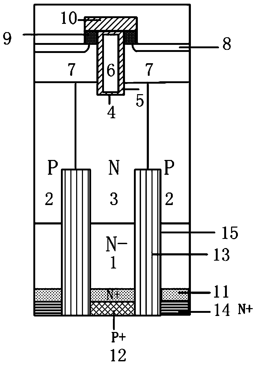
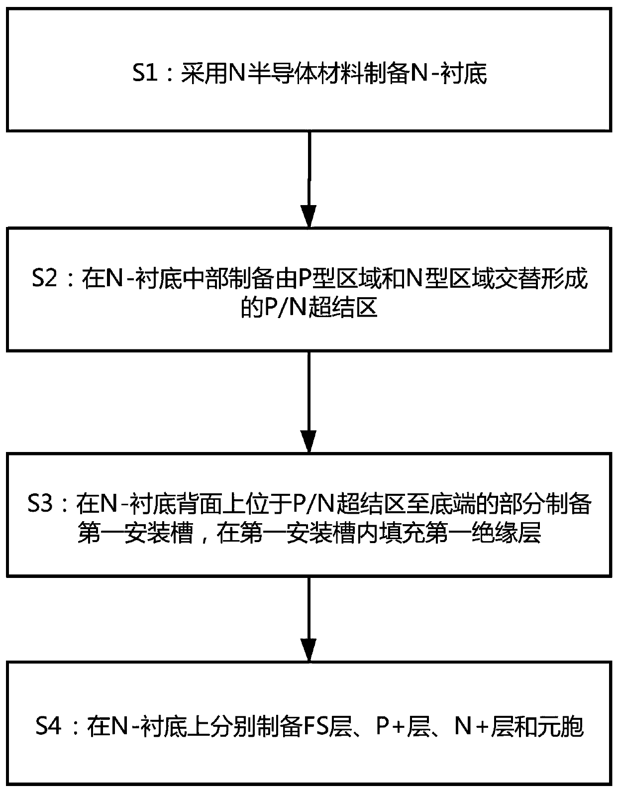
[0029] see Figure 1-2 , the IGBT device structure in this embodiment includes an N-substrate 1, a super junction region disposed on the N-substrate 1, a cell disposed on the upper end of the super junction region, and a FS disposed on the lower end of the N-substrate 1 layer 11, the P+ layer 12 disposed on the lower end of the N-substrate 1, the N+ layer 14 disposed on the lower end of the N-substrate 1, and the filling layer disposed on the N-substrate 1, the filling layer includes 1, and the first insulating layer 13 filled in the first installation groove 15.

[0030] Here, the N-substrate 1, the superjunction region, the cell, the FS layer 11, the P+ layer 12, and the N+ layer 14 can ensure the withstand voltage of t...


PUM


Abstract

The invention provides an IGBT device structure and a preparation method thereof, which belong to the technical field of semiconductor power devices and process manufacturing. The IGBT device structure comprises an N-substrate, a super junction region, cells, an FS layer, a P + layer, an N + layer and a filling layer. According to the invention, the N-substrate, the super junction region, the cells, the FS layer, the P + layer and the N + layer can guarantee the withstand voltage of the device; a first mounting groove is formed in the N-substrate; the first mounting groove is filled with a first insulating layer; the first insulating layer is made of a high-K insulating material, so that when the device is turned on, the hole carrier density in the FS layer is improved, the IGBT region andthe MOSFET region are effectively isolated; and the on-resistance of the device is effectively reduced, and the snapback phenomenon when the device is turned on is inhibited.

Description

technical field [0001] The invention belongs to the technical field of semiconductor power devices and process manufacturing, and relates to an IGBT device structure and a preparation method thereof. Background technique [0002] IGBT, the Chinese name is Insulated Gate Bipolar Transistor, which is a Darlington structure formed by the combination of field effect transistor MOSFET and bipolar power transistor BJT. It has the advantages of high MOSFET input impedance, simple driving, and high switching speed, and has the advantages of BJT current With the advantages of high density, low saturation voltage, and strong current handling capability, it is an ideal full-control device. The frequency characteristic is between MOSFET and power transistor, and it can work normally in the frequency range of tens of kHz. Insulated bipolar transistor IGBTInsulate Gate Bipolar Transistor, since its invention, has become a mainstream switching device in the field of medium and high power e...

Claims


Application Information

Patent Timeline
IPC IPC(8): H01L29/739H01L29/06H01L21/331
CPCH01L29/0634H01L29/0649H01L29/0653H01L29/66348H01L29/7397
Inventor 程炜涛程庆彪潘克学
Owner 潘克学
Learn More