
Manufacturing method of silicon-on-insulator PMOS device

A technology of silicon-on-insulator and manufacturing method, which is applied in the field of manufacturing silicon-on-insulator PMOS devices, and can solve problems such as excessive device leakage and device leakage

Inactive Publication Date: 2020-08-25
CSMC TECH FAB2 CO LTD
View PDF0 Cites 0 Cited by
  • Summary
  • Abstract
  • Description
  • Claims
  • Application Information

AI Technical Summary

Problems solved by technology

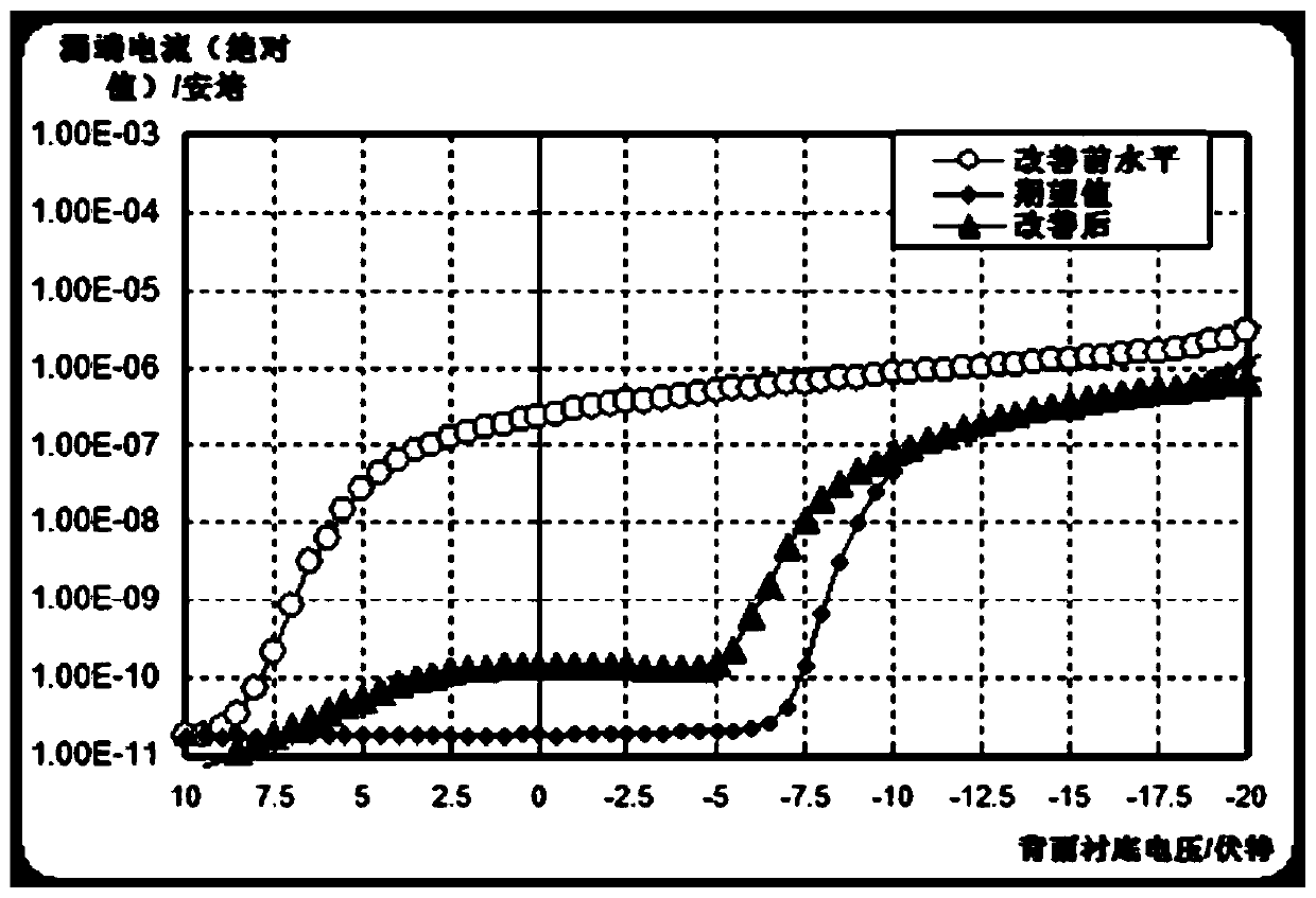
When the turn-on voltage of the back gate is small, there will be a problem of excessive leakage of the device (when the substrate has some unknown induced charges, it is easy to form a parasitic channel near the BOX on the top layer of silicon, resulting in leakage of the device on the front, resulting in circuit effective)

Method used


Image

  • Manufacturing method of silicon-on-insulator PMOS device
  • Manufacturing method of silicon-on-insulator PMOS device
  • Manufacturing method of silicon-on-insulator PMOS device

Examples


Embodiment Construction

[0021] In order to facilitate the understanding of the present invention, the present invention will be described more fully below with reference to the associated drawings. A preferred embodiment of the invention is shown in the drawings. However, the present invention can be embodied in many different forms and is not limited to the embodiments described herein. Rather, these embodiments are provided so that the disclosure of the present invention will be thorough and complete.

[0022] Unless otherwise defined, all technical and scientific terms used herein have the same meaning as commonly understood by one of ordinary skill in the technical field of the invention. The terms used herein in the description of the present invention are for the purpose of describing specific embodiments only, and are not intended to limit the present invention. As used herein, the term "and / or" includes any and all combinations of one or more of the associated listed items.

[0023] It wil...


PUM

PropertyMeasurementUnit
Resistivityaaaaaaaaaa

Abstract

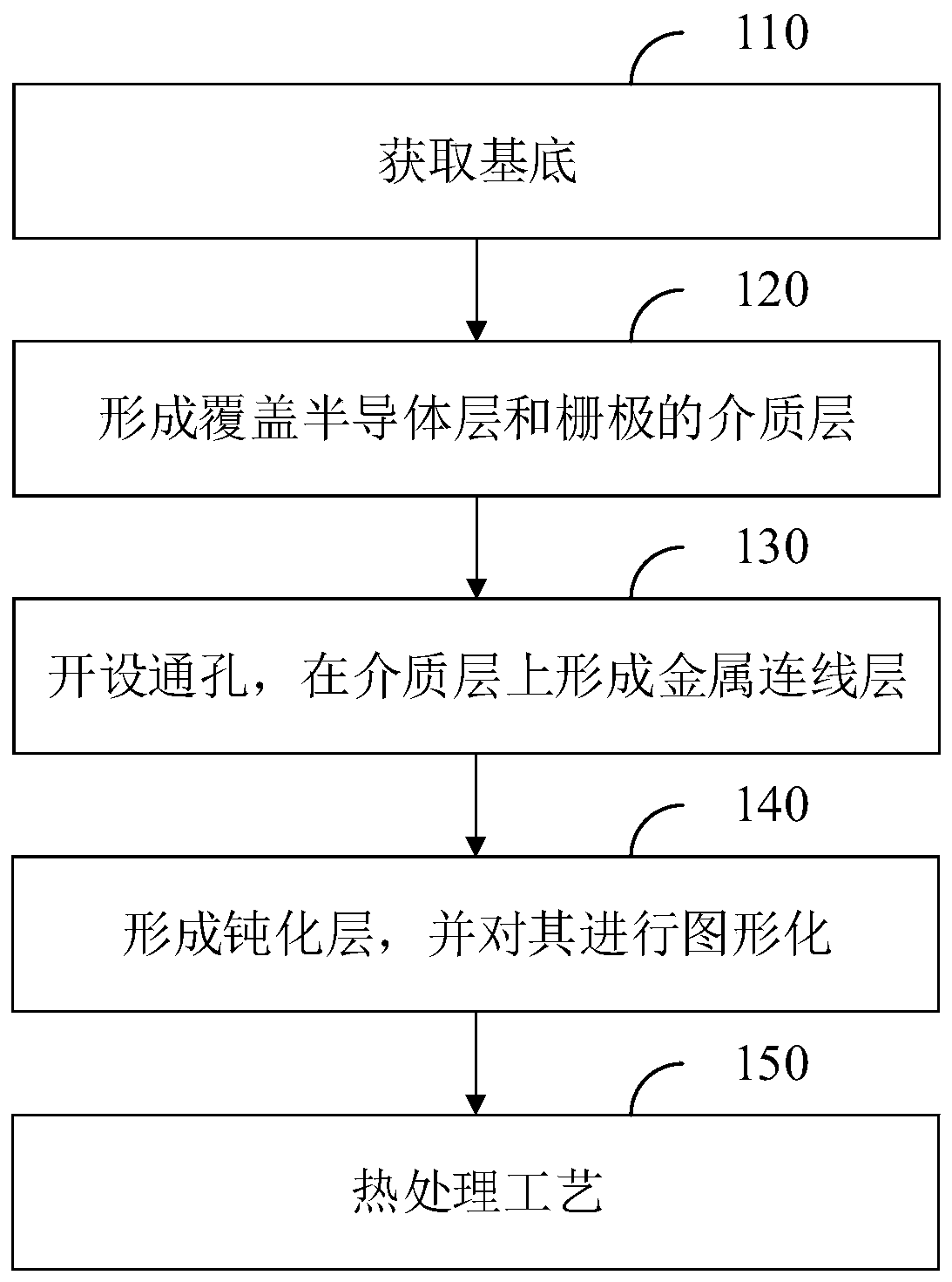
The invention relates to a manufacturing method of a silicon-on-insulator PMOS device. The method comprises the steps that a base is acquired, wherein the base comprises a substrate, a buried oxide layer on the substrate and a semiconductor layer on the buried oxide layer, an N well, a source electrode region and a drain electrode region are formed in the semiconductor layer, and a gate electrodeis formed on the semiconductor layer; a dielectric layer covering the semiconductor layer and the gate electrode is formed; a plurality of through holes are formed in the dielectric layer, a metal connecting line layer is formed on the dielectric layer, and the source region, the drain region and the gate electrode are led out by the metal connecting line layer through conductive media filled in the through holes; a passivation layer is formed on the metal connecting line layer, the passivation layer is patterned through photoetching and etching, and etching is dry etching; and then a heat treatment process is carried out, wherein the process temperature of the heat treatment is greater than 420 DEG C. By increasing the process temperature of heat treatment, the back gate turn-on voltage of the PMOS tube is effectively increased, and the problem of excessive electric leakage of the PMOS device in the traditional process is solved.

Description

technical field [0001] The invention relates to the technical field of semiconductor integrated circuits, in particular to a method for manufacturing a silicon-on-insulator PMOS device. Background technique [0002] Compared with ordinary bulk silicon devices, SOI (Silicon-On-Insulator, silicon on insulator) devices have a series of advantages such as good isolation effect, no latch-up effect, good radiation resistance effect, small parasitic capacitance, and small chip design area. [0003] Generally, SOI includes 3 levels: substrate (handle wafer), buried oxide layer (BOX) on the substrate, and semiconductor layer (SOI) on the buried oxide layer. For PMOS transistors on SOI substrates, viewing from the bottom up There is a parasitic device: the gate of the parasitic device is the Si substrate, the buried oxide layer is the gate oxide of the parasitic device, the source region and the drain region of the parasitic device are P+ in the semiconductor layer, and the N well in ...

Claims


Application Information

Patent Timeline
IPC IPC(8): H01L29/78H01L21/336H01L21/762H01L21/324
CPCH01L21/324H01L21/7624H01L29/66477H01L29/78
Inventor 胡金节
Owner CSMC TECH FAB2 CO LTD
Learn More