Welding additive trailing ultrasonic impact device and operation method

An ultrasonic impact and follow-welding technology, applied in the field of 3D printing, can solve the problems of difficulty in ensuring that the follow-weld impact point is located in the high-temperature plastic zone of welding, without considering the adjustment of the follow-weld impact lag time, and increasing the moving load of welding additive equipment. Easy operation and intelligent control, stable ultrasonic impact treatment process, high ultrasonic transmission efficiency

Active Publication Date: 2020-08-28
NANCHANG UNIV
View PDF6 Cites 6 Cited by
  • Summary
  • Abstract
  • Description
  • Claims
  • Application Information

AI Technical Summary

Problems solved by technology

Make the ultrasonic vibrator easy to deviate from the resonance
[0010] 2 The existing welding ultrasonic impact method is: the welding torch is welded above the weldment, and the ultrasonic impact head is impacted behind the weldment, which is only suitable for single-layer welds
Therefore, it cannot be applied to welding additive manufacturing
[0011] 3 No consideration is given to the adjustment of the interval between the welding point and the welding impact point: relevant research in the industry has proved that the welding impact point is located in the high-temperature plastic zone of welding, and the effect is the best. The optimal distance is also different, but the existing technology does not consider adjusting the distance between the welding point and the welding impact point
That is, without considering the adjustment of the lag time of the welding impact, it is difficult to ensure that the w

Method used


Image

  • Welding additive trailing ultrasonic impact device and operation method
  • Welding additive trailing ultrasonic impact device and operation method
  • Welding additive trailing ultrasonic impact device and operation method

Examples


Embodiment Construction

[0047] Below the present invention is further described:

[0048] see Figure 1-7 ,

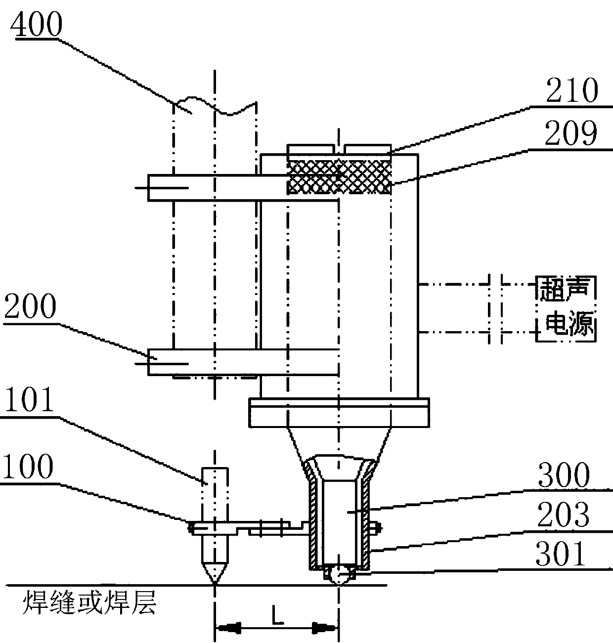
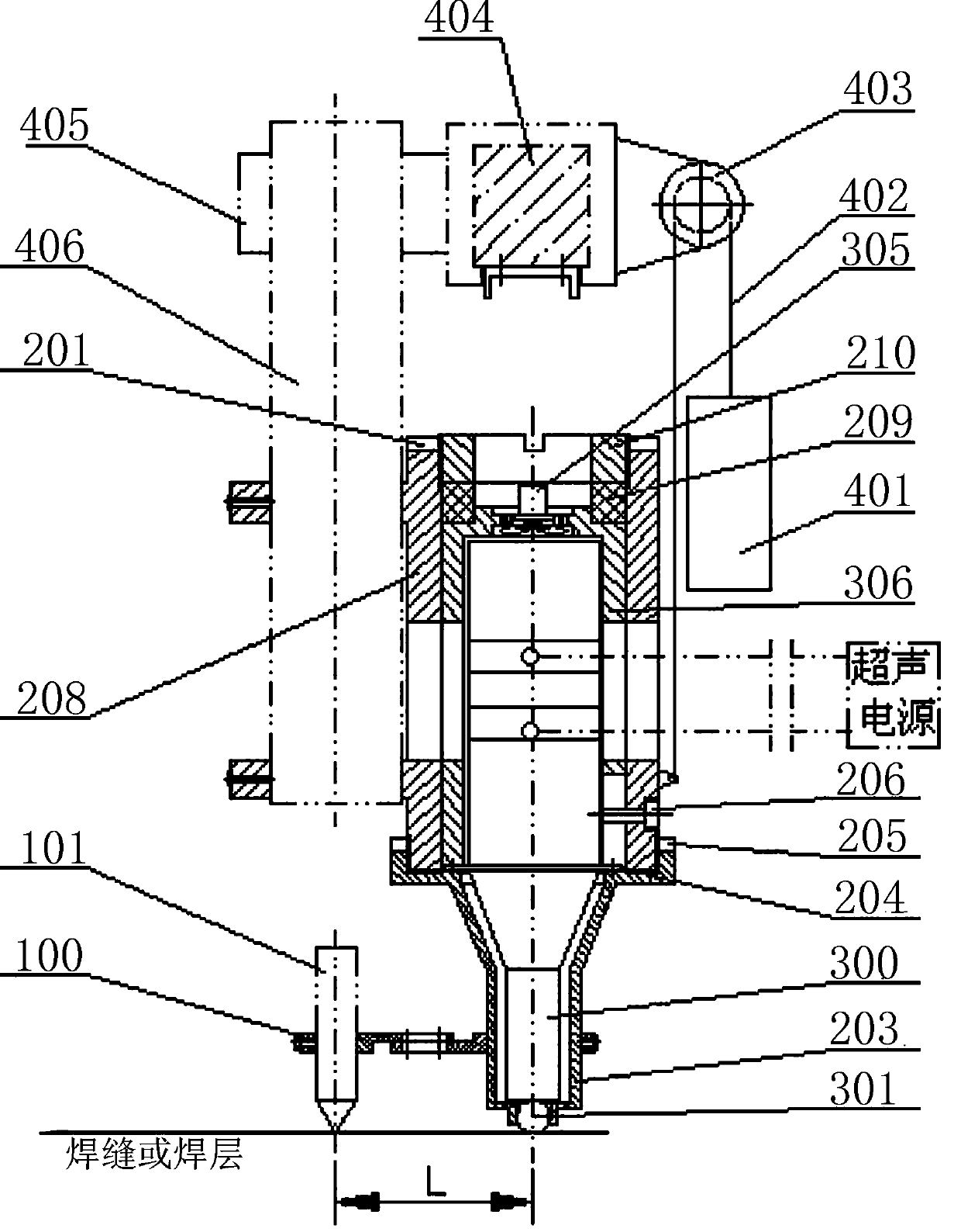
[0049] The invention discloses an ultrasonic impact device for welding additive materials with welding. The device description: the connecting sleeve 208 is connected with the 3D moving column 406 of the gantry welding machine, the ultrasonic vibrator 300 is floating on the connecting sleeve assembly 200, and the front end of the ultrasonic vibrator horn 302 Ultrasonic impact treatment of the welding layer by the steel ball 301 reduces the friction of the ultrasonic vibrator moving with the welding and avoids the deflection of the ultrasonic vibrator; the upper part of the connecting sleeve is equipped with a pre-tightening ring 210 and an elastic ring 209 for adjusting the pre-pressure of the ultrasonic impact; The thickness of the welding layer or weld seam changes, the load of the ultrasonic vibrator is stabilized, and the resonant frequency is stabilized. The lower part of the connectio...


PUM


Abstract

The invention relates to the technical field of 3D printing, in particular to a welding additive trailing ultrasonic impact device and an operation method. The welding additive trailing ultrasonic impact device comprises a welding gun, a connecting sleeve assembly and an ultrasonic vibrator, the welding gun is connected with the connecting sleeve assembly through a welding gun connecting assembly,the ultrasonic vibrator is sleeved with the connecting sleeve assembly, a steel ball at the bottom end of the ultrasonic vibrator penetrates through the connecting sleeve assembly and then makes contact with a weld layer for trailing ultrasonic impact treatment on the weld layer. According to the welding additive trailing ultrasonic impact device and the operation method, damage energy of seismicwaves to a building can be converted, the influence of the seismic waves on a building foundation is blocked, and then vibration of the overground part of the building is avoided; ultrasonic impact real-time impact is carried out on the weld layer or a weld seam, and the modern welding additive manufacturing requirement can be met; the requirements of different impact pressures and unevenness ofweld pieces can be met; the distance between an ultrasonic impact position and a welding gun position can be adjusted according to requirements to adapt to adjustment of trailing time lag time; and the ultrasonic transmission efficiency is high, and the ultrasonic impact treatment effect is good.

Description

technical field [0001] The invention relates to the technical field of 3D printing, in particular to an ultrasonic impact device and an operation method for welding additive materials with welding. Background technique [0002] With the development of science and technology, additive manufacturing technology is surging. Compared with other additive manufacturing, welding additive manufacturing has low cost and high efficiency, especially the advantages of some large-scale component additive manufacturing are more obvious. Therefore, welding additive manufacturing grows faster . In addition, welding technology is also widely used in national defense and military industry, national economy and people's livelihood, and is widely used in ships, vehicles, pressure vessels, etc. However, after all, welding is locally heated and melted, and then cooled to form a weld or weld layer. It is essentially a local metallurgical process, which will inevitably produce many factors such as ...

Claims


Application Information

Patent Timeline
IPC IPC(8): B23K20/10B33Y10/00B33Y30/00
CPCB23K20/10B33Y10/00B33Y30/00Y02P10/25
Inventor 朱政强王官明吴蔺锋陈燕琴
Owner NANCHANG UNIV
Why Eureka
Try Eureka