Automatic feeding and discharging device for circuit board laser drilling

An automatic loading and unloading and laser drilling technology, which is applied in laser welding equipment, welding/welding/cutting items, manufacturing tools, etc., can solve the problems of circuit board wrinkles, uneven suction board, low efficiency, etc., and reduce the loading and unloading time , Improve the efficiency of loading and unloading, and improve the effect of utilization rate

Pending Publication Date: 2020-08-28
深圳市本川智能设备有限公司
View PDF0 Cites 4 Cited by
  • Summary
  • Abstract
  • Description
  • Claims
  • Application Information

AI Technical Summary

Problems solved by technology

[0002] The circuit board is a necessary part for electronic products. It is mainly used to connect and install various electronic components and to describe and route the distance of each electronic device; at present, the process of laser drilling of circuit boards in major circuit board manufacturers Among them, the loading and unloading of circuit boards is done manually without automated production equipment. Manual loading and unloading is not only inefficient, but also takes a long time; and it is easy to cause wrinkles on the circuit board when manually loading and unloading the circuit board. Damage the circuit board or even cause the circuit board to be scrapped; at the same time, when the workers suspend their work due to their own reasons, the laser drilling device must also be shut down, which reduces the utilization rate of the laser drilling device; When the board is drilled, dust and debris will be generated. After drilling a circuit board, it is necessary to manually remove dust from the workbench of the laser drilling machine, which is extremely troublesome. If the dust removal operation is not performed, the dust and debris will be Adhesion to the circuit board that is subsequently drilled, causing the suction board to be uneven, and affecting the laser processing quality of the circuit board

Method used


Image

  • Automatic feeding and discharging device for circuit board laser drilling
  • Automatic feeding and discharging device for circuit board laser drilling
  • Automatic feeding and discharging device for circuit board laser drilling

Examples


Embodiment Construction

[0015] Further detailed explanation through specific implementation mode below:

[0016] The reference signs in the accompanying drawings of the specification include:

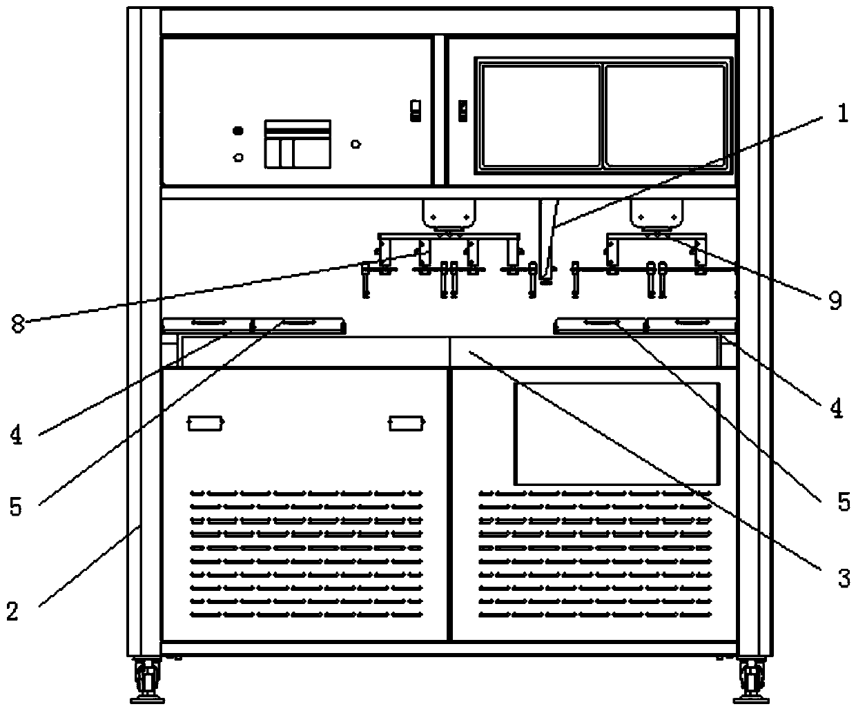
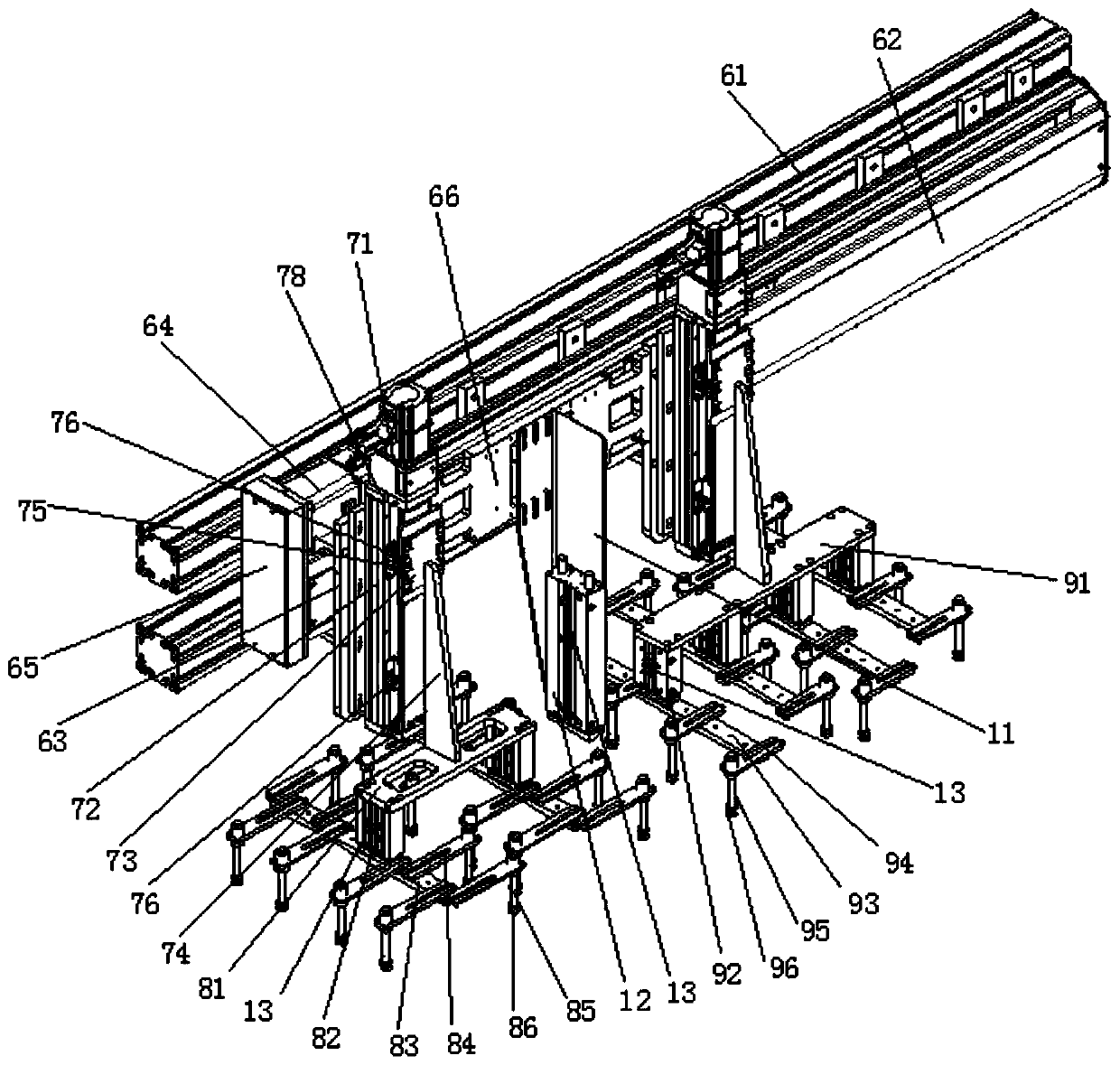
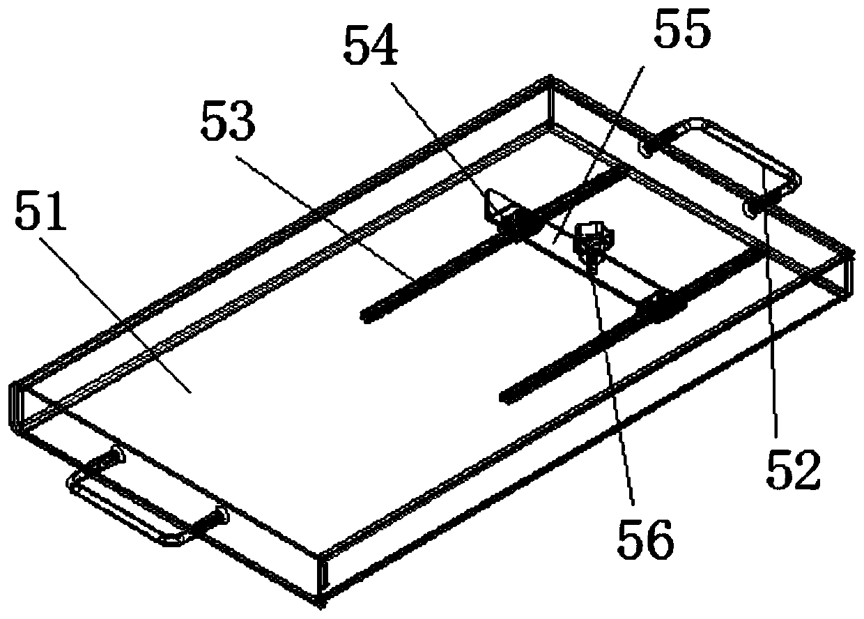
[0017] 1. Sweeping module, 11. Connection plate, 12. Sweeping cylinder, 13. Magnetic switch, 2. Rack, 3. Laser drilling machine, 4. Bracket, 5. Material box assembly, 51. Tooling material box , 52. Handle, 53. Guide rail, 54. Guide block, 55. Baffle plate, 56. Fixing bolt, 6. Moving component, 61. Fixed rod, 62. Slide rail, 63. Slider, 64. Servo motor, 65. Reducer, 66. Support plate, 7. Pushing module, 71. Servo motor, 72. Vertical guide rail, 73. Vertical slider, 74. Fixed plate, 75. Inductive sheet, U-shaped photoelectric sensor, 8. Down Material module, 81. Loading mounting plate, 82. Loading cylinder, 83. Loading connecting rod, 84. Loading installation rod, 85. Loading connecting pipe, 86. Loading suction cup, 9. Loading module, 91 .Feeding installation plate, 92. Feeding cylinder, 93. Feeding connectin...


PUM


Abstract

The invention discloses an automatic feeding and discharging device for circuit board laser drilling. The automatic feeding and discharging device comprises a rack, a controller and a laser drilling machine, wherein the laser drilling machine is mounted at the lower part of the rack. The automatic feeding and discharging device further comprises a material conveying assembly and a material box assembly. According to the automatic feeding and discharging device for circuit board laser drilling, automatic feeding and discharging operation can be carried out on circuit boards at the position of the laser drilling machine through a feeding module and a discharging module of the material conveying assembly; meanwhile, a sweeping module can sweep and remove dust on a working table of the laser drilling machine; circuit boards of various sizes can be placed as required through the material box assembly; according to the automatic feeding and discharging device for circuit board laser drilling, the feeding and discharging efficiency of the circuit boards can be improved, the feeding and discharging time of the circuit boards is shortened, meanwhile, the circuit boards cannot be folded andbent, so that the quality of the product is effectively improved, the rejection rate of circuit board drilling is reduced, and the utilization rate of the laser drilling machine is improved; and in addition, the working table of the laser drilling machine can be automatically swept, so that great convenience is brought to a user.

Description

technical field [0001] The invention relates to a circuit board production equipment, in particular to a circuit board laser drilling automatic loading and unloading device. Background technique [0002] The circuit board is a necessary part for electronic products. It is mainly used to connect and install various electronic components and to describe and route the distance of each electronic device; at present, the process of laser drilling of circuit boards in major circuit board manufacturers Among them, the loading and unloading operations of circuit boards are all carried out manually without automated production equipment. Manual loading and unloading is not only inefficient, but also takes a long time; and it is easy to cause wrinkles on the circuit board when manually loading and unloading the circuit board. Damage to the circuit board or even cause the circuit board to be scrapped; at the same time, when the workers suspend their work due to their own reasons, the l...

Claims


Application Information

Patent Timeline
Patent Type & Authority Applications(China)
IPC IPC(8): B23K26/382B23K26/70B23K101/36
CPCB23K26/382B23K26/702B23K2101/36
Inventor 滕艳宇
Owner 深圳市本川智能设备有限公司
Why Eureka
Try Eureka