
Robot trajectory tracking control method based on visual guidance

A visual guidance and trajectory tracking technology, which is applied in the direction of program control manipulators, manipulators, manufacturing tools, etc., can solve the problems of principle error, poor real-time performance, and limited measurement frequency, and achieve poor trajectory accuracy, arc error reduction, straight line The effect of error reduction

Active Publication Date: 2020-08-28
NANJING UNIV OF AERONAUTICS & ASTRONAUTICS
View PDF8 Cites 19 Cited by
  • Summary
  • Abstract
  • Description
  • Claims
  • Application Information

AI Technical Summary

Problems solved by technology

The laser head of the laser tracker can only emit one beam of laser light, which scans the target balls installed on the end effector in sequence to obtain the position information of all target balls, and can solve the attitude of the end effector. When the end effector moves, it needs to consider each The acquisition time of the position information of each target ball, and the time difference in the acquisition of the position information of each target point, so there is a principle error, the measurement frequency is limited, and the real-time performance is poor.
Not only that, in complex working conditions, once the laser is blocked, it cannot continue to track the target ball, and cannot continue to measure

Method used


Image

  • Robot trajectory tracking control method based on visual guidance
  • Robot trajectory tracking control method based on visual guidance
  • Robot trajectory tracking control method based on visual guidance

Examples


Embodiment Construction

[0038] Embodiments of the present invention will be further described in detail below in conjunction with the accompanying drawings.

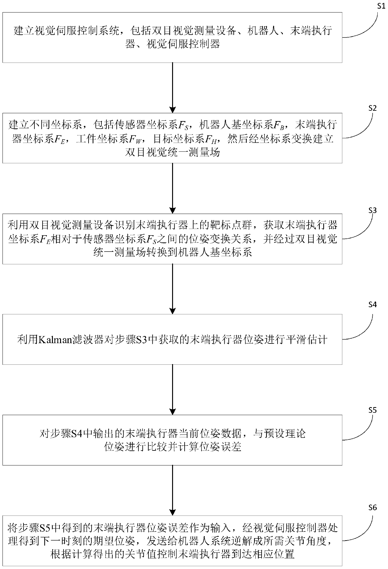
[0039] Such as Figure 1-4 Shown, the present invention is a kind of robot trajectory tracking control method based on visual guidance, which comprises the following steps:

[0040] Step S1: Establish a visual servo control system, including binocular visual measurement equipment, a robot, an end effector, and a visual servo controller;

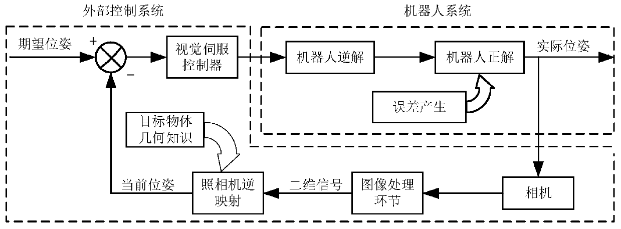
[0041] Specifically, the actual pose of the robot end effector is tracked and measured in real time by binocular vision measurement equipment, and a closed-loop loop is added to form a closed-loop control system. The pose error obtained by the closed-loop feedback is processed by the visual servo controller to obtain the next moment. The expected pose is sent to the robot system for inverse analysis into the required joint angles, and the motor is controlled to reach the corresponding position according to th...


PUM


Abstract

The invention relates to a robot trajectory tracking control method based on visual guidance. The method comprises the following steps: establishing a robot visual servo control system; establishing abinocular vision unified measurement field; carrying out observing by using a binocular vision device to obtain a pose transformation relationship between an end effector coordinate system and a measurement coordinate system, and converting the pose transformation relationship to a robot base coordinate system through the binocular vision measurement field; carrying out smooth estimation on the observed pose of an end effector by utilizing a Kalman filter; calculating the pose error of the end effector; and designing a visual servo controller based on fuzzy PID, processing the pose error to obtain an expected pose at the next moment, and sending the expected pose to a robot system to control the end effector to move. The technical scheme is oriented to the field of flexible machining of aerospace large parts and the application requirements of robot high-precision machining equipment, the pose of the end effector is sensed in real time through a visual sensor, so that a closed-loop feedback system is formed, and the trajectory motion precision of a six-degree-of-freedom series robot is greatly improved.

Description

technical field [0001] The invention belongs to the technical field of robot trajectory tracking control, and in particular relates to a vision-guided robot trajectory tracking control method. Background technique [0002] In recent years, industrial robots have become more and more widely used in the aerospace field due to their advantages of high flexibility, low cost, and high workspace / floor area ratio. However, the processing and assembly of large aircraft parts in the aerospace manufacturing industry are often High precision is required. The current robot performs processing operations according to the preset motion trajectory. Due to the low overall precision of the robot, it is difficult to guarantee the processing accuracy and surface quality. Therefore, a high-precision trajectory tracking control method for robots is needed. [0003] The invention patent with the notification number CN106671103A discloses a milling robot control method and system, which uses a la...

Claims


Application Information

Patent Timeline
Patent Type & Authority Applications(China)
IPC IPC(8): B25J9/16
CPCB25J9/1664B25J9/1697
Inventor 李波韦学文田威傅宇文廖文和张霖胡俊山崔光裕李宇飞
Owner NANJING UNIV OF AERONAUTICS & ASTRONAUTICS
Learn More