A pressure test tubular mouth sealing device

A pressure test and sealing device technology, which is applied to the sealing of engines, pipe components, pipes/pipe joints/fittings, etc., can solve the problems of inconvenient operation and poor sealing effect, and achieve the advantages of convenient material acquisition, low cost and strong versatility Effect

Active Publication Date: 2022-02-22
HARBIN BOILER
View PDF6 Cites 0 Cited by
  • Summary
  • Abstract
  • Description
  • Claims
  • Application Information

AI Technical Summary

Problems solved by technology

[0005] The purpose of the present invention is to solve the problems of inconvenient operation and poor sealing effect in the existing nozzle sealing device for pressure test

Method used


Image

  • A pressure test tubular mouth sealing device
  • A pressure test tubular mouth sealing device

Examples


specific Embodiment approach 1

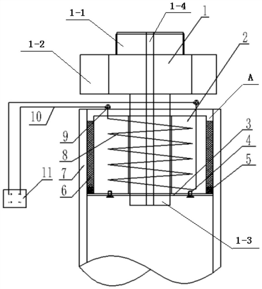
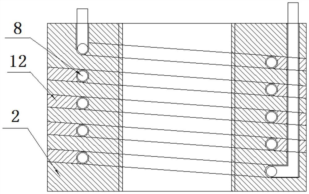
[0018] Specific implementation mode one: combine figure 1 Describe this embodiment, a pressure test tubular mouth sealing device of this embodiment includes an inner core 1, an outer core 2, an end piece 3, a sealing rope 5 and a sealing body 6, the outer core 2 is installed at the bottom of the inner core 1, and the outer The core 2 is embedded in the tubular mouth 7, the inner core 1, the outer core 2 and the tubular mouth 7 are arranged coaxially, a sealing gap A is left between the outer wall of the outer core 2 and the inner wall of the tubular mouth 7, and the end piece 3 can be It is disassembled and installed on the lower end surface of the outer core 2, and the end piece 3 is in interference fit with the inner side wall of the tubular mouth 7, and the sealing rope 5 and the sealing body 6 are sealed in the sealing gap A sequentially from bottom to top.

[0019] In this embodiment, the inner core 1 is connected to the outer core 2 by threaded connection.

specific Embodiment approach 2

[0020] Specific implementation mode two: combination figure 1 Describe this embodiment, the inner core 1 of this embodiment comprises external connection segment 1-1, screw segment 1-2 and internal connection segment 1-3, external connection segment 1-1, screw segment 1-2 and internal connection Sections 1-3 are sequentially fixed and integrated from top to bottom, and the outer connection section 1-1, the screw section 1-2 and the inner connection section 1-3 are provided with a central through hole 1-4 along the axial direction. In this way, the external connection section 1-1 is an external thread structure for connecting with the outside, the internal connection section 1-3 is an external thread structure for connecting with the outer core 2, and the screw section 1-2 is for the convenience of Tightened hexagonal prism. Other compositions and connections are the same as in the first embodiment.

[0021] The central through hole 1-4 of this embodiment is used to inject pr...

specific Embodiment approach 3

[0022] Specific implementation mode three: combination figure 1 This embodiment will be described. The end piece 3 of this embodiment is made of copper sheet, and the thickness of the end piece 3 is less than 1 mm. Such setting has elastic deformation, and the thickness of the end piece is less than 1mm, so that when the sealing body formed with the inner core 1 and the outer core 2 enters the tubular opening 7, it can be uniformly and freely deformed into a concave bottom shape, and when it encounters a gap smaller than the sealing member gap Foreign matter can pass through by itself, which increases the versatility, and other components and connections are the same as those in the first or second embodiment.


PUM

PropertyMeasurementUnit
Thicknessaaaaaaaaaa
The inside diameter ofaaaaaaaaaa

Abstract

A pressure test tubular mouth sealing device relates to a tubular mouth sealing device. The invention aims to solve the problems of inconvenient operation and poor sealing effect existing in the existing nozzle sealing device for pressure test. The present invention comprises an inner core (1), an outer core (2), an end piece (3), a sealing rope (5) and a sealing body (6), the outer core (2) is installed at the bottom of the inner core (1), and the outer The core (2) is embedded in the tubular mouth (7), the inner core (1), the outer core (2) and the tubular mouth (7) are arranged coaxially, the outer side wall of the outer core (2) and the tubular mouth (7) There is a sealing gap (A) between the inner side walls, the end piece (3) is detachably installed on the lower end surface of the outer core (2), and there is an interference fit between the end piece (3) and the inner side wall of the tubular mouth (7) , the sealing rope (5) and the sealing body (6) are packaged in the sealing gap (A) sequentially from bottom to top. The present invention is used for tubular mouth sealing.

Description

technical field [0001] The invention relates to a sealing device. It specifically relates to a tubular mouth sealing device for hydrostatic test and air pressure test, and belongs to the field of pressure test. Background technique [0002] In the manufacturing process of some mechanical equipment such as pressure vessels and boiler equipment, hydraulic pressure and air pressure tests are required, and castings containing oil circuits also need to be tested for hydraulic pressure and air pressure before machining. Before the hydraulic or air pressure test, the tubular mouth of the equipment needs to be blocked. The current traditional method is to use the sealing plate for welding. This sealing method requires a lot of work, and it is easy to change the organizational structure of the nozzle. If necessary, the nozzle needs to be processed twice, which increases the processing cost and reduces work efficiency; the second traditional method is that the nozzle is built with a ...

Claims


Application Information

Patent Timeline
IPC IPC(8): F16L55/11F16J15/10
CPCF16L55/1116F16J15/104
Inventor 韩基文程木森张广磊
Owner HARBIN BOILER
Why Eureka
Try Eureka