High-temperature-resistant optical fiber strain sensor

An optical fiber strain and sensor technology, applied in the field of sensors, can solve the problems of unusable, small strain detection range and temperature detection range of optical fiber temperature strain sensor, achieve simple structure, improve strain sensitivity, and expand strain detection range and temperature detection range. Effect

Inactive Publication Date: 2020-08-28
NORTHWEST UNIV(CN)
View PDF2 Cites 4 Cited by
  • Summary
  • Abstract
  • Description
  • Claims
  • Application Information

AI Technical Summary

Problems solved by technology

[0005] The above-mentioned optical fiber temperature strain sensor mainly has a small strain detection range and temperature detection range, the strain detection range is 0-200με, and the temperature detection range is room temperature to 80°C, so it cannot be used in an environment with a large strain detection range and temperature detection range

Method used


Image

  • High-temperature-resistant optical fiber strain sensor
  • High-temperature-resistant optical fiber strain sensor
  • High-temperature-resistant optical fiber strain sensor

Examples


Embodiment 1

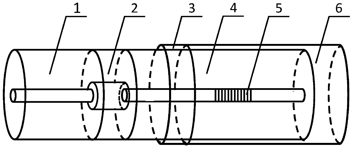
[0022] exist figure 1 Among them, the high-temperature resistant optical fiber strain sensor of this embodiment is composed of a first single-mode optical fiber 1, a hollow optical fiber 2, a high-temperature ceramic adhesive layer 3, a second single-mode optical fiber 4, a thermally regenerated fiber grating 5, and a capillary glass tube 6.

[0023] The inner diameter of the hollow fiber 2 of the present embodiment is 19 μm, and the left end of the hollow fiber 2 is axially welded with a first single-mode optical fiber 1 by laser welding, and arc welding can also be used, and the right end of the hollow fiber 2 is axially welded with a second fiber. The single-mode optical fiber 4, the first single-mode optical fiber 1 and the second single-mode optical fiber 4 are commodities sold in the market, the first single-mode optical fiber 1 and the second single-mode optical fiber 4 are SMF-28, and the core diameter is 8.2 μm , the cladding diameter is 125 μm, the splicing surface o...

Embodiment 2

[0029] The inner diameter of the hollow fiber 2 in this embodiment is 8 μm, the left end of the hollow fiber 2 is axially welded with a first single-mode fiber 1 by laser, and the right end of the hollow fiber 2 is axially connected with a second single-mode fiber 4 by laser fusion. The models of a single-mode optical fiber 1 and the second single-mode optical fiber 4 are the same as in Embodiment 1, the splicing surface of the first single-mode optical fiber 1 and the hollow-core optical fiber 2, the hollow-core optical fiber 2, the hollow-core optical fiber 2 and the second single-mode optical fiber The splicing surfaces of 4 together form a Fabry-Perot interference cavity. A thermally regenerated Bragg grating 5 is written on the second single-mode optical fiber 4 , the length of the thermally regenerated Bragg grating 5 is 10 mm, and the center wavelength is 1500 nm.

[0030] The right side of the second single-mode optical fiber 4 is coaxially bonded in the capillary glas...

Embodiment 3

[0033] The inner diameter of the hollow fiber 2 in this embodiment is 70 μm, the left end of the hollow fiber 2 is axially welded with a first single-mode fiber 1 by laser, and the right end of the hollow fiber 2 is axially connected with a second single-mode fiber 4 by laser fusion. The models of a single-mode optical fiber 1 and the second single-mode optical fiber 4 are the same as in Embodiment 1, the splicing surface of the first single-mode optical fiber 1 and the hollow-core optical fiber 2, the hollow-core optical fiber 2, the hollow-core optical fiber 2 and the second single-mode optical fiber The splicing surfaces of 4 together form a Fabry-Perot interference cavity. A thermally regenerated Bragg grating 5 is written on the second single-mode optical fiber 4 , the length of the thermally regenerated Bragg grating 5 is 10 mm, and the center wavelength is 1600 nm.

[0034] The right side of the second single-mode optical fiber 4 is coaxially bonded in the capillary gla...


PUM

PropertyMeasurementUnit
lengthaaaaaaaaaa
wavelengthaaaaaaaaaa
diameteraaaaaaaaaa

Abstract

The invention discloses a high-temperature-resistant optical fiber strain sensor. The left end of a hollow-core optical fiber is welded with a first single-mode optical fiber, and the right end of thehollow-core optical fiber is bonded with a second single-mode optical fiber positioned in a capillary glass tube by using high-temperature ceramic glue; a high-temperature ceramic adhesive layer is formed after the high-temperature ceramic glue is solidified, a Fabry-Perot interference cavity is formed by the splicing surface of the first single-mode optical fiber and the hollow-core optical fiber and the splicing surfaces of the hollow-core optical fiber, the hollow-core optical fiber and the second single-mode optical fiber, and a thermal regeneration Bragg grating is inscribed on the second single-mode optical fiber. According to the invention, the problem of temperature and strain double-parameter cross sensitivity is effectively solved. Compared with a traditional optical fiber strain sensor, the strain sensitivity of the strain sensor is improved, the strain detection range is 0-700 [mu][epsilon], the temperature detection range is room temperature to 1000 DEG C, the strain detection range and the temperature detection range are expanded, and the optical fiber strain sensor has the advantages of the simple structure, the small size, high sensitivity and the like, and can beused as a strain sensor.

Description

technical field [0001] The invention belongs to the technical field of sensors, and in particular relates to optical fiber strain sensors. Background technique [0002] The aerodynamic heating of a hypersonic vehicle in flight is a transient heat conduction process. The temperature changes rapidly. The more severe the aerodynamic heating, the greater the temperature gradient inside the aircraft skin, which will cause the thermal deformation and thermal stress of the skin. The thermal stress exceeds When the limit value of the skin material is exceeded, the skin or parts will be plastically deformed or even damaged, resulting in a flight accident of the aircraft. When analyzing the temperature field of the aircraft structure, it is necessary to analyze the thermal stress of the aircraft skin to provide reliable reference data for the optimization and design of aircraft skin materials. It is a key technology to ensure the safe operation of the aircraft and prolong its service...

Claims


Application Information

Patent Timeline
Patent Type & Authority Applications(China)
IPC IPC(8): G01B11/16
CPCG01B11/161
Inventor 杨杭洲刘继辛国国田琴何宇栋韩钊
Owner NORTHWEST UNIV(CN)
Why Eureka
Try Eureka