
Laser light source and laser projection equipment

A laser light source and laser technology, applied in optics, instruments, projection devices, etc., can solve problems such as poor heat dissipation effect and inability to meet the thermal conductivity requirements of miniaturized lasers

Pending Publication Date: 2020-08-28
QINGDAO HISENSE LASER DISPLAY CO LTD
View PDF5 Cites 6 Cited by
  • Summary
  • Abstract
  • Description
  • Claims
  • Application Information

AI Technical Summary

Problems solved by technology

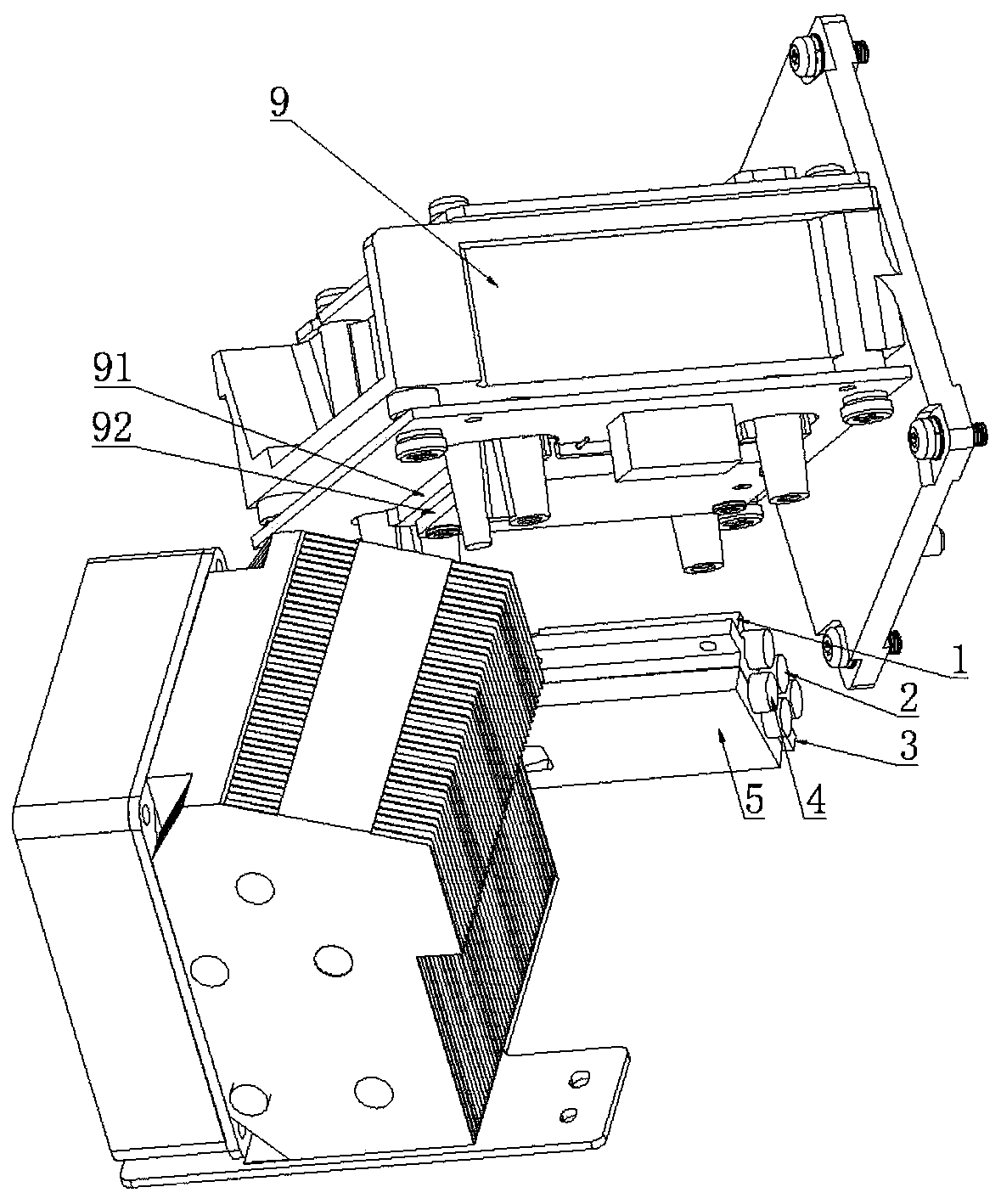
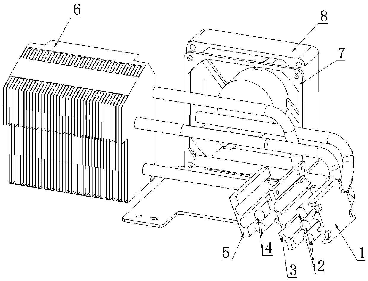
[0005] This application provides a laser light source and laser projection equipment to solve the technical problem that the current heat dissipation device cannot meet the heat conduction requirements of miniaturized lasers and the heat dissipation effect is poor

Method used


Image

  • Laser light source and laser projection equipment
  • Laser light source and laser projection equipment
  • Laser light source and laser projection equipment

Examples


Embodiment Construction

[0023] In order to enable those skilled in the art to better understand the technical solutions in the present application, the technical solutions in the embodiments of the present application will be clearly and completely described below in conjunction with the drawings in the embodiments of the present application. Obviously, the described The embodiments are only some of the embodiments of the present application, not all of them. Based on the embodiments in this application, all other embodiments obtained by persons of ordinary skill in the art without creative efforts shall fall within the scope of protection of this application.

[0024] At present, laser projection equipment tends to be more and more miniaturized. First, the volume of the light source system needs to be small enough to achieve the design goal. The laser is used as the light-emitting part of the light source system. In order to reduce the volume of the laser, the MCL laser is used instead of the tradit...


PUM

PropertyMeasurementUnit
Bending angleaaaaaaaaaa

Abstract

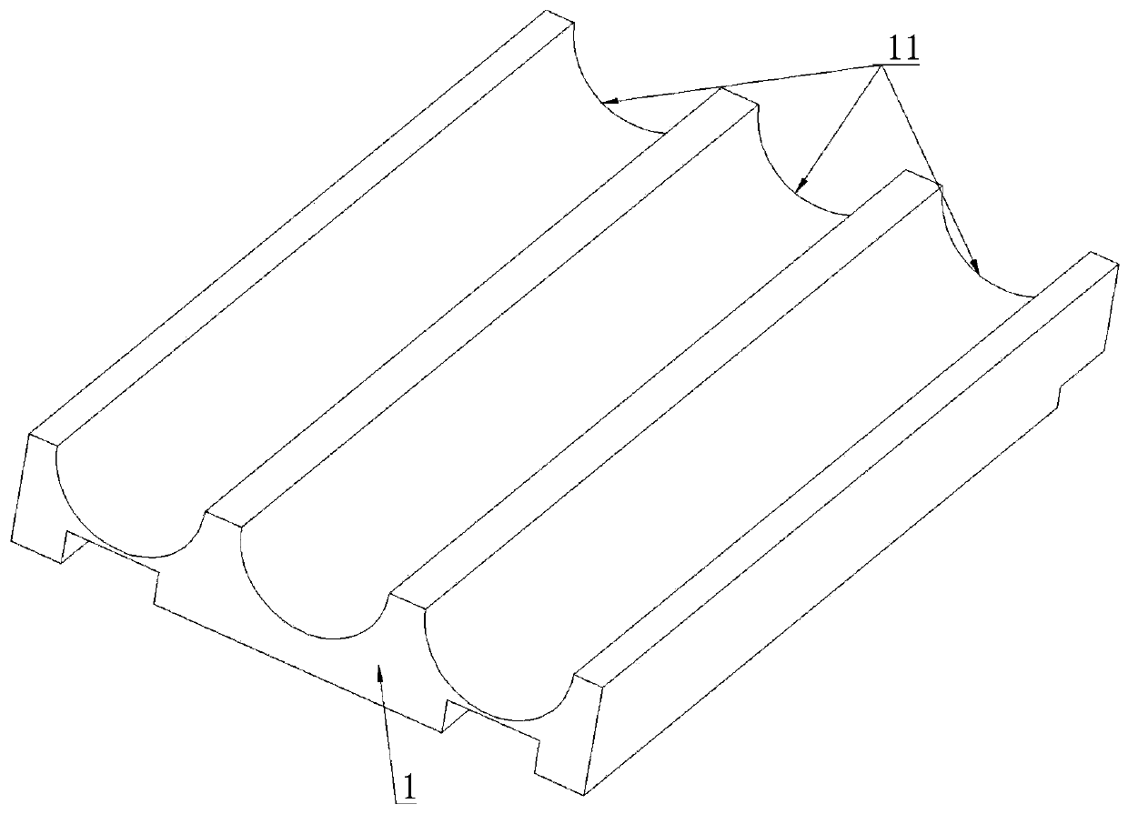
The invention discloses a laser light source and laser projection equipment. The laser light source comprises a laser device and a laser device heat dissipation device, wherein a heat sink is arrangedon the side, facing the heat dissipation device, of the laser device, the heat dissipation device comprises a heat conduction layer and a fin module, the heat sink makes contact with the heat conduction layer, the heat conduction layer comprises at least two layers of heat conduction blocks, a plurality of heat pipes are arranged between the adjacent heat conduction blocks, each heat pipe comprises a hot end, a cold end and a bent part for connecting the hot end and the cold end, the hot end is connected with the adjacent heat conduction blocks, the fin module comprises a plurality of parallel heat dissipation fins, and the cold ends vertically penetrate through the heat dissipation fins respectively. According to the invention, the laser light source performs heat dissipation on the laser device in a heat conduction mode, and the heat pipes are arranged in the heat conduction layer in a laminated mode by designing the contact mode of the heat conduction layer and the heat pipes, so that the heat transfer requirement of the laser device is met; and the optimal combination of the heat conduction layer and the heat dissipation fins is achieved by bending the heat pipes, so that heatof the laser device is rapidly conducted to the fin module, the heat dissipation efficiency is improved, and the design target of miniaturization of the laser module is achieved.

Description

technical field [0001] The present application relates to the technical field of laser heat dissipation, in particular to a laser light source and laser projection equipment. Background technique [0002] Laser projection equipment generally consists of a light source system, lighting system and lens system. The laser in the light source system is used to convert electrical energy into light energy, and then project the laser onto the screen through the lighting system and lens system to project laser images. When the laser converts electrical energy into light energy, the conversion efficiency is usually about 40%, that is to say, the remaining 60% of the electrical energy will be converted into heat energy, which makes the laser continue to heat up. As the temperature of the laser increases, the luminous efficiency of the laser will show a downward trend, so it is necessary to cool down the temperature of the laser to ensure the luminous efficiency of the laser. [0003] ...

Claims


Application Information

Patent Timeline
IPC IPC(8): G03B21/16G03B21/20
CPCG03B21/16G03B21/2033
Inventor 崔雷邢哲
Owner QINGDAO HISENSE LASER DISPLAY CO LTD
Learn More