
Oil refining additive drying and conveying device

A conveying device and drying technology, which is applied in the directions of drying gas arrangement, drying solid materials, drying, etc., can solve the problems of uneven drying, heating, affecting drying effect, etc., and achieve the effect of improving efficiency and synchronizing drying degree.

Inactive Publication Date: 2020-09-01
蒋利群
View PDF0 Cites 0 Cited by
  • Summary
  • Abstract
  • Description
  • Claims
  • Application Information

AI Technical Summary

Problems solved by technology

[0003] The refining aid is conveyed by a screw rod, and the refining aid wrapped inside cannot be heated synchronously with the surrounding refining aid, resulting in uneven drying and affecting the drying effect

Method used


Image

  • Oil refining additive drying and conveying device
  • Oil refining additive drying and conveying device
  • Oil refining additive drying and conveying device

Examples


Embodiment 1

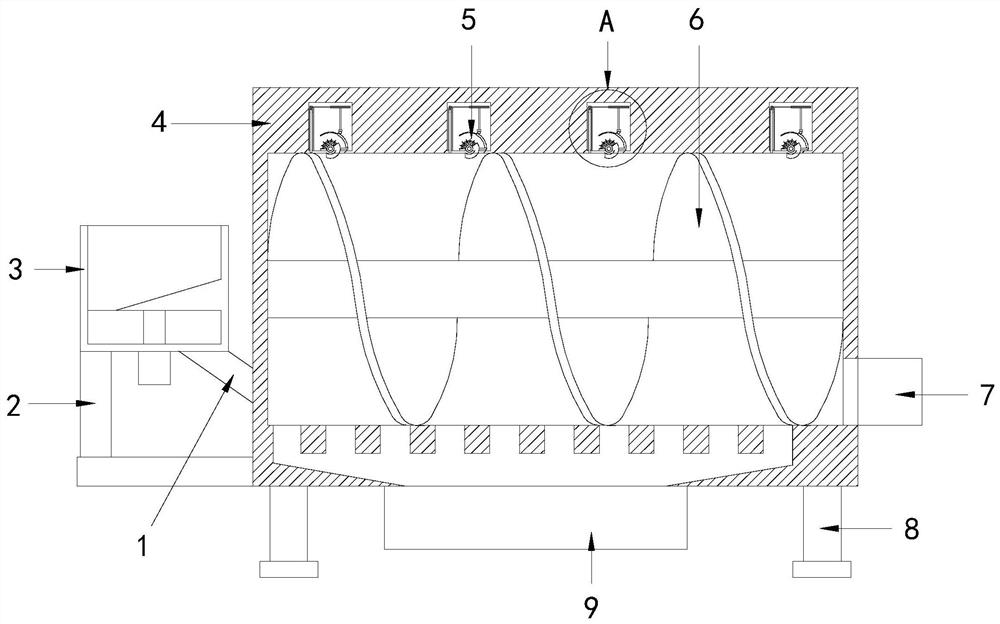
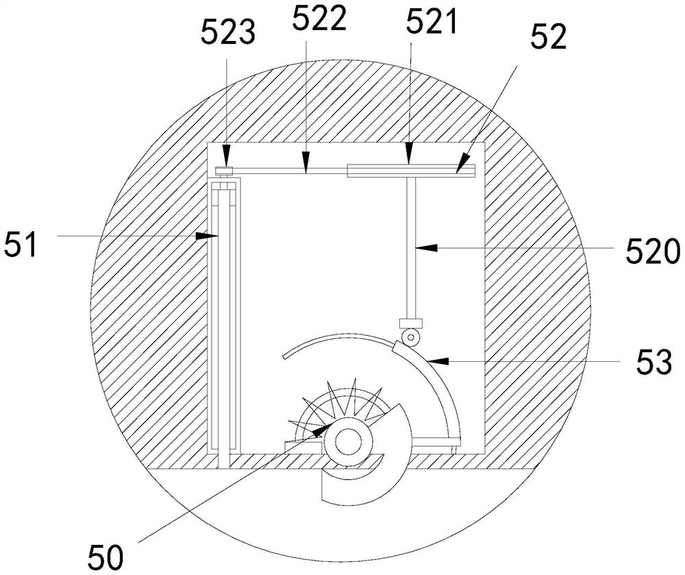
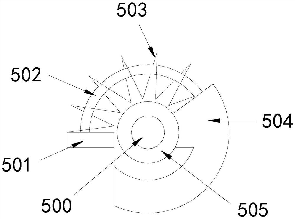
[0026] see Figure 1-5 , the present invention provides a technical solution for drying and conveying equipment for oil refining aids: its structure includes a feed pipe 1, a bracket 2, a material cylinder 3, a drying cylinder 4, an auxiliary structure 5, a screw rod 6, an outlet 7, a foot 8, and a heating device 9. The bottom of the drying cylinder 4 is connected with a heating device 9, the two ends of the drying cylinder 4 are welded with feet 8, one end of the drying cylinder 4 is provided with an outlet 7, and the other end is connected with the barrel 3 through the feeding pipe 1 , the barrel 3 is connected to the side of the drying barrel 4 through the bracket 2, the inner wall of the drying barrel 4 is provided with a mounting groove, and an auxiliary structure 5 is installed in the mounting groove, and the auxiliary structure 5 includes a power structure 50, a moving structure 51. Enlarging structure 52, transmission structure 53, the power structure 50 is connected t...

Embodiment 2

[0029] see Figure 1-5, the present invention provides a technical solution for drying and conveying equipment for oil refining aids: its structure includes a feed pipe 1, a bracket 2, a material cylinder 3, a drying cylinder 4, an auxiliary structure 5, a screw rod 6, an outlet 7, a foot 8, and a heating device 9. The bottom of the drying cylinder 4 is connected with a heating device 9, the two ends of the drying cylinder 4 are welded with feet 8, one end of the drying cylinder 4 is provided with an outlet 7, and the other end is connected with the barrel 3 through the feeding pipe 1 , the barrel 3 is connected to the side of the drying barrel 4 through the bracket 2, the inner wall of the drying barrel 4 is provided with a mounting groove, and an auxiliary structure 5 is installed in the mounting groove, and the auxiliary structure 5 includes a power structure 50, a moving structure 51. Enlarging structure 52, transmission structure 53, the power structure 50 is connected to...


PUM


Abstract

The invention discloses an oil refining additive drying and conveying device. The oil refining additive drying and conveying device structurally comprises a feeding pipe, a support, a barrel, a dryingcylinder, auxiliary structures, a screw rod, an outlet, supporting legs and a heating device, wherein the heating device is connected to the bottom of the drying cylinder, the supporting legs are welded to two ends of the drying cylinder, one end of the drying cylinder is provided with the outlet, the other end of the drying cylinder communicates with the barrel, the barrel is connected to the side face of the drying cylinder through the support, the inner wall of the drying cylinder is provided with installation grooves, and the auxiliary structures are installed in the installation grooves.The oil refining additive drying and conveying device has the advantages that the movement of the screw rod is utilized as power to make air outlet pipes stretch into additives for heating drying, itcan be guaranteed that the internal and external drying degrees of the additives are the same, and the drying quality and efficiency are improved; and the air outlet pipes can automatically retract so that the movement of the screw rod cannot be hindered.

Description

technical field [0001] The invention relates to the technical field of oil additives, in particular to a drying and conveying device for oil refining additives. Background technique [0002] Oil refining is a process of distilling crude oil or other oils without changing the molecular structure. In the process of oil refining, crude oil must go through a series of processes to obtain various useful petroleum products. Generally refers to petroleum refining, that is, cracking crude oil into kerosene, gasoline, diesel, heavy oil and other fuels suitable for internal combustion engines, and producing chemical raw materials, such as olefins, aromatics, etc. The current refinery is generally an oil-chemical combination type refinery factory. Refining aids have the functions of ensuring stable operation, inhibiting equipment corrosion, preventing equipment blockage, prolonging the operation cycle, improving processing capacity, and protecting the activity and selectivity of crack...

Claims


Application Information

Patent Timeline
IPC IPC(8): F26B17/20F26B21/00F26B25/02
CPCF26B17/20F26B21/004F26B25/02
Inventor 蒋利群
Owner 蒋利群
Learn More