Device and method for measuring lightning impact force and lightning fracture damage of carbon fiber laminates

A carbon fiber layer, measuring device technology, applied in the direction of measuring device, force/torque/work measuring instrument, measuring electricity, etc., can solve the problem that the instantaneous relationship cannot be accurately given, the impact force dispersion is large, and the lightning impact force cannot be fully characterized. Aircraft structure impact force, etc.

Active Publication Date: 2021-04-27
XI AN JIAOTONG UNIV
View PDF6 Cites 1 Cited by
  • Summary
  • Abstract
  • Description
  • Claims
  • Application Information

AI Technical Summary

Problems solved by technology

However, in the process of lightning attachment, is the lightning impact force formed due to the ionization of channel gas caused by high voltage related to the fracture and delamination damage of carbon fibers? The current public literature cannot give a good explanation
At the same time, the lightning damage calculated based on the thermoelectric coupling modeling of the tested carbon fiber composite laminate can only reflect the lightning damage caused by the Joule heat injected by the lightning current after the lightning strikes the attachment point, while for other mechanical effects, such as the lightning damage before the attachment point The lightning impact force and the implosion impact force formed by the pyrolysis gas of the tested carbon fiber composite laminate resin cannot be characterized; in addition, the invention patent ZL 201510579759.4 discloses the method of lightning impact force of carbon fiber composite materials, but there are the following problems:
[0004] (1) The clamping method of the tested carbon fiber composite laminate is upper and lower clamping, that is, the lightning strike is injected from one surface of the tested carbon fiber composite laminate and flows out from the other plane of the tested carbon fiber composite laminate. The lightning impact force measured by the clamping method cannot fully represent the impact force when the actual large aircraft structure is subjected to lightning
[0005] (2) Below the carbon fiber laminate is a metal plate electrode. A circular or square slot for installing an insulating plate is opened in the center of the plate electrode, and a slot for installing a piezoelectric sensor is opened in the center of the insulating plate. The surface of the piezoelectric sensor and the The surface of the insulating plate is flat and in close contact with the tested carbon fiber composite laminate. However, due to the light weight of the carbon fiber laminate in the experimental study, the contact between the carbon fiber laminate and the impact piezoelectric sensor is not in firm contact, resulting in The measured impact force has a large dispersion, and it is impossible to accurately characterize the lightning impact force of lightning strikes on carbon fiber laminates
[0006] (3) Because the lightning impact piezoelectric sensor is placed in the strong electromagnetic environment of the carbon fiber laminate lightning impact, the lightning impact signal extracted by the piezoelectric sensor has strong electromagnetic interference, which causes a large deviation in the impact force measurement
[0007] (4) During the action of lightning strikes and carbon fiber composite materials, the instantaneous relationship between lightning impact force and lightning current response time cannot be accurately given, which directly affects the research on the lightning damage mechanism of lightning strikes and carbon fiber composite materials and the design of carbon fiber lightning protection materials and protective structures.

Method used


Image

  • Device and method for measuring lightning impact force and lightning fracture damage of carbon fiber laminates
  • Device and method for measuring lightning impact force and lightning fracture damage of carbon fiber laminates
  • Device and method for measuring lightning impact force and lightning fracture damage of carbon fiber laminates

Examples


Embodiment Construction

[0037] The present invention will be described in further detail below in conjunction with specific examples, but not as a limitation of the present invention.

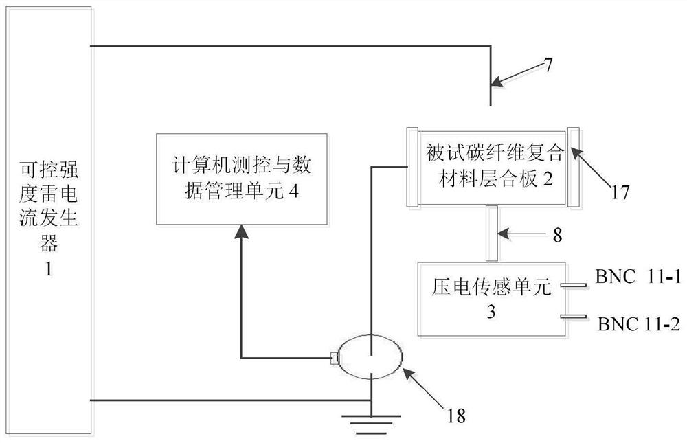
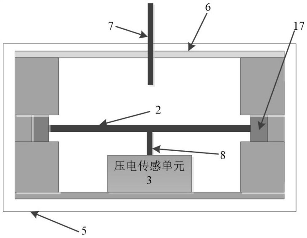
[0038] see figure 1 , the measuring device of lightning strike impact force and carbon fiber lightning fracture damage with common mode interference suppression performance under strong electromagnetic interference of the present invention includes a controllable intensity lightning current generator 1, a carbon fiber composite material laminate 2 to be tested, a piezoelectric sensor Unit 3 and computer measurement and control and data management unit 4. The high-voltage end of the controllable intensity lightning current generator 1 is connected to the metal rod-shaped electrode 7 installed on the insulating cover plate 6 in the experimental fixture 5, and the metal rod-shaped electrode 7 is perpendicular to the upper surface of the carbon fiber composite laminate 2 to be tested. For the center of the tested carbon ...


PUM


Abstract

The invention discloses a measurement device and method for lightning impact force and lightning fracture damage of a carbon fiber laminated plate with common-mode interference suppression performance. Through a certain length and a certain cross-section of the lightning impact force transmission insulating rod, it is transmitted to the piezoelectric sensing unit with a shielded shell, so that the measurement of the impact force of the tested carbon fiber composite laminate can be free from the influence of strong lightning current electromagnetic interference; through By adjusting the amplitude of the lightning current output by the controllable intensity lightning current generator, the mathematical analytical formula between the lightning impact force and the lightning current parameters of the tested carbon fiber composite laminate can be obtained; at the same time, by changing the tested carbon fiber The distance between the composite laminate and the piezoelectric sensor can obtain the response time characteristics of the lightning impact force, which provides theoretical support for the mechanism research of the lightning damage effect of the tested carbon fiber composite laminate.

Description

technical field [0001] The invention belongs to the measurement technology of the mechanical effect of lightning strikes on materials, and relates to a method for measuring the impact force of lightning strikes on carbon fiber composite materials, in particular to a device and method for measuring lightning strike force and lightning fracture damage of carbon fiber laminates. Background technique [0002] Carbon fiber composite materials have the characteristics of low density, high strength, high modulus, high temperature resistance, chemical corrosion resistance, etc., and are widely used in various fields such as aerospace, military and civil industries. With the increasing use of carbon fiber composite materials in aircraft structures such as large aircraft, high-intensity lightning strikes will cause serious damage such as fiber fracture, resin pyrolysis, and deep delamination of carbon fiber composite materials. Therefore, the lightning damage and lightning protection ...

Claims


Application Information

Patent Timeline
Patent Type & Authority Patents(China)
IPC IPC(8): G06F17/10G01L5/00G01L1/16G01R31/00G01R31/12G01R1/18
CPCG01L1/16G01L5/00G01R1/18G01R31/00G01R31/1263
Inventor 孙晋茹陈景亮姚学玲李亚丰
Owner XI AN JIAOTONG UNIV
Why Eureka
Try Eureka