Verification test block suitable for plane wave ultrasonic imaging system demonstration and design method thereof

A technology of ultrasonic imaging system and design method, which is applied in the direction of material analysis, design optimization/simulation, and calculation using sonic/ultrasonic/infrasonic waves, and can solve problems such as inability to verify instrument performance, limited thickness of test blocks, and inability to be too thick. , to achieve the effect of displaying and testing the performance of the instrument, the demonstration program is fast, and the thickness is not limited.

Active Publication Date: 2020-09-01
苏州无损检测协会 +1
View PDF2 Cites 0 Cited by
  • Summary
  • Abstract
  • Description
  • Claims
  • Application Information

AI Technical Summary

Problems solved by technology

[0004] But such demonstration test block and imaging process have the following defects: 1. The imaging speed of the demonstration process is slow, and the probe needs to be moved from the two directions of the length and width of the demonstration test block; 2. The depth of the specific character groove in the demonstration test block is fixed. value or a few limited specific values, the performance of the instrument ca...

Method used


Image

  • Verification test block suitable for plane wave ultrasonic imaging system demonstration and design method thereof
  • Verification test block suitable for plane wave ultrasonic imaging system demonstration and design method thereof
  • Verification test block suitable for plane wave ultrasonic imaging system demonstration and design method thereof

Examples


Embodiment Construction

[0037]In order to enable those skilled in the art to better understand the technical solutions of the present invention, the technical solutions in the embodiments of the present invention will be clearly and completely described below in conjunction with the drawings in the embodiments of the present invention. Obviously, the described implementation Examples are only some of the embodiments of the present invention, not all of them. Based on the embodiments of the present invention, all other embodiments obtained by persons of ordinary skill in the art without making creative efforts shall fall within the protection scope of the present invention.

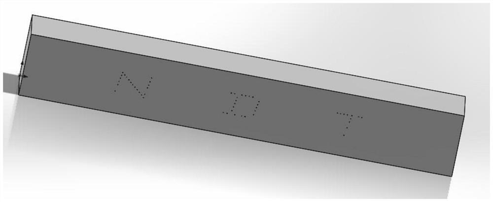
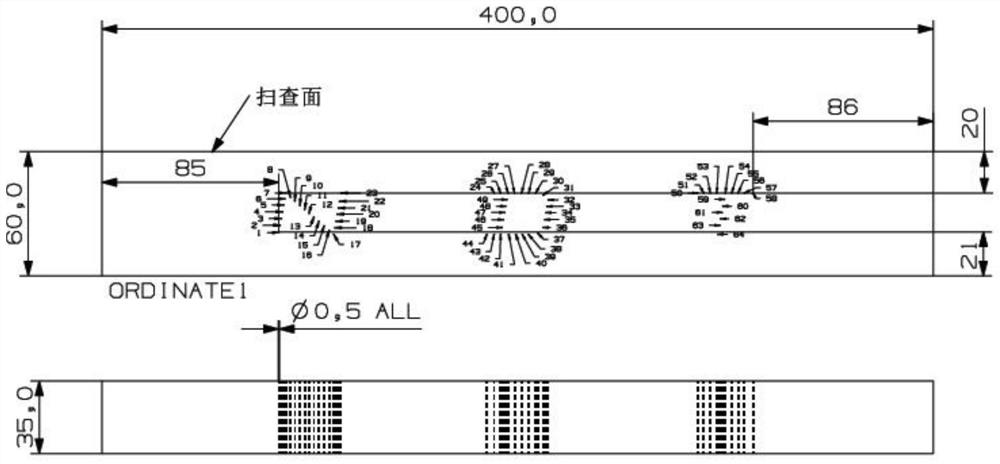
[0038] refer to Figure 2-7 , the verification test block applicable to the demonstration of the plane wave ultrasonic imaging system in this embodiment is designed by the following design method, specifically including the following steps:

[0039] 1) Determine the size of the test block

[0040] Determine the size of the test...


PUM

PropertyMeasurementUnit
Diameteraaaaaaaaaa
Slopeaaaaaaaaaa

Abstract

The invention relates to a design method of a verification test block suitable for plane wave ultrasonic imaging system demonstration. The design method comprises the following steps: determining thesize of the test block; determining character positions; determining fonts and font sizes of the characters; determining the position of the transverse through hole: drawing the shape of the characterthrough multiple line segments or arcs, dividing the multiple line segments and/or arcs into a plurality of parts, drawing a circle representing the transverse through hole at each division point, determining the position of the transverse through hole on the test block, and obtaining a character sketch; and carrying out verification: importing the character sketch into ultrasonic simulation software, placing a transverse through hole with a designed size in each circular area, selecting plane wave imaging, carrying out simulation calculation, and determining the effectiveness of the test block. According to the design method of the verification test block suitable for plane wave ultrasonic imaging system demonstration, the through transverse through hole is formed in the thickness direction of the test block to form the character, when the verification test block performs plane wave imaging, the probe only needs to move in the length direction of the test block, the demonstration program speed is high, and the thickness of the test block is not limited.

Description

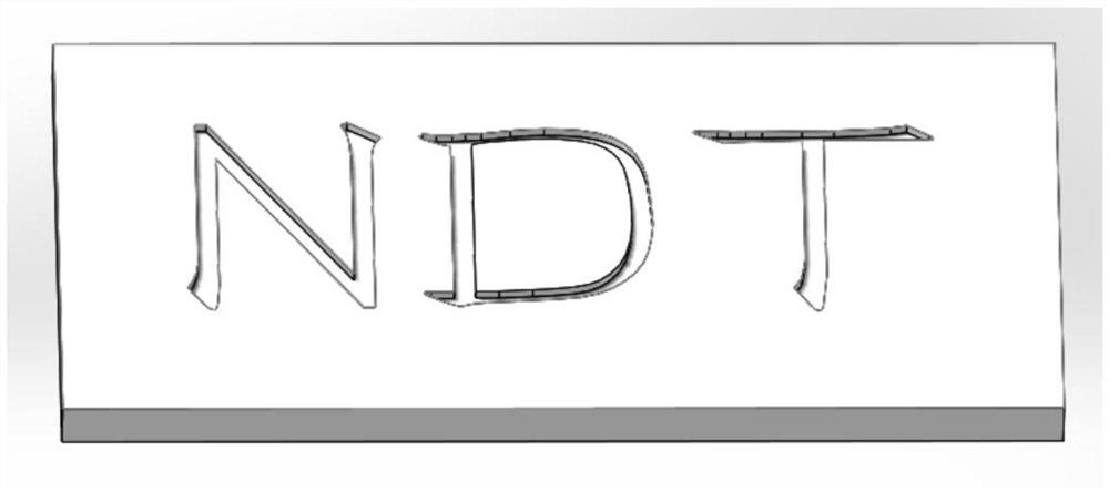
technical field [0001] The invention specifically relates to a design method of a verification test block suitable for the demonstration of a plane wave ultrasonic imaging system and a verification test block suitable for the demonstration of a plane wave ultrasonic imaging system prepared according to the design method. Background technique [0002] In recent years, with the increasingly powerful computer hardware level and the increasingly mature software algorithm, phased array ultrasonic imaging has been more and more widely used in industry. C-scan imaging based on phased array ultrasound is also widely used in testing the performance of ultrasonic testing equipment and promoting the brand of instrument manufacturers or non-destructive testing units. In the existing phased array ultrasonic demonstration test block, the demonstration characters are engraved on the thin metal plate in the form of shallow grooves, such as figure 1 shown. During the demonstration, a linea...

Claims


Application Information

Patent Timeline
IPC IPC(8): G06F40/166G06F40/106G06F40/109G06F30/20G01N29/30
CPCG06F40/166G06F40/106G06F40/109G06F30/20G01N29/30
Inventor 刘晓睿顾玄严海童忠贵刘金宏
Owner 苏州无损检测协会
Why Eureka
Try Eureka