Particle carrier band forming system and process

A molding process and carrier tape technology, applied in belts, packaging, other household appliances, etc., can solve the problems of sudden change of hole position, deformation of carrier tape receiving direction, economic loss of enterprises, etc., to reduce heat loss and avoid user complaints , the effect of speeding up the drying speed

Inactive Publication Date: 2020-09-04
JIANGYIN WINPACK TECH
View PDF0 Cites 2 Cited by
  • Summary
  • Abstract
  • Description
  • Claims
  • Application Information

AI Technical Summary

Problems solved by technology

[0004] ①The conventional heating step generally uses an extruder to heat and extrude the masterbatch particles. Before production, the masterbatch particles of the extruder need to be baked by a drying system to reduce the water content. The traditional drying method is to use a heater to heat Air, the blower blows hot air into the drying barrel filled with raw material particles. The air outlet of the blower is connected to the exhaust pipe. However, this drying method is easy to bring out debris, dust or foreign impurities in the raw material particles, and blow them into the air in a large area, causing pollution; at the same time, the traditional drying method will directly send hot air with When the water vapor is discharged into the air together, the heating time and the number of heating times at the same time will increase, resulting in an increase in energy consumption;
[0005] ②The masterbatch particles are easy to form carbon deposits in the barrel of the extruder, which needs regular cleaning. When cleaning, it is necessary to discharge the conductive masterbatch particles in the drying barrel, add clean particles, heat and extrude several times, and then put the conductive masterbatch Pour the particles back into the drying barrel. This cleaning method will cause the particles to accumulate at the discharge port, resulting in mixing; at the same time, it will take a long time to repeatedly discharge, feed, dry, and adjust the temperature; therefore, it takes a long time. A feeding mechanism that can save the process of repeated discharging and feeding, and can prevent particles from accumulating at the discharge port;
[0006] ③In the conventional manufacturing process, the carrier tape is wound directly after punching and stripping, and the quality of the carrier tape is not tested. However, during the punching process, the carrier tape sometimes has a sudden change in the hole position, which affects the normal use of customers. , so that customer complaints or even product returns occur, causing huge economic losses to the company; and the surface of the carrier tape is not completely flat, sometimes there will be bumps, which will cause the carrier tape to get stuck at the fast place where the thickness of the receiving material is limited, and the receiving material The pulling force of the cable causes the carrier tape to be deformed or even stuck in the receiving direction, and the carrier tape is scrapped, resulting in a decrease in the production yield and a waste of materials;

Method used


Image

  • Particle carrier band forming system and process
  • Particle carrier band forming system and process
  • Particle carrier band forming system and process

Examples


Embodiment Construction

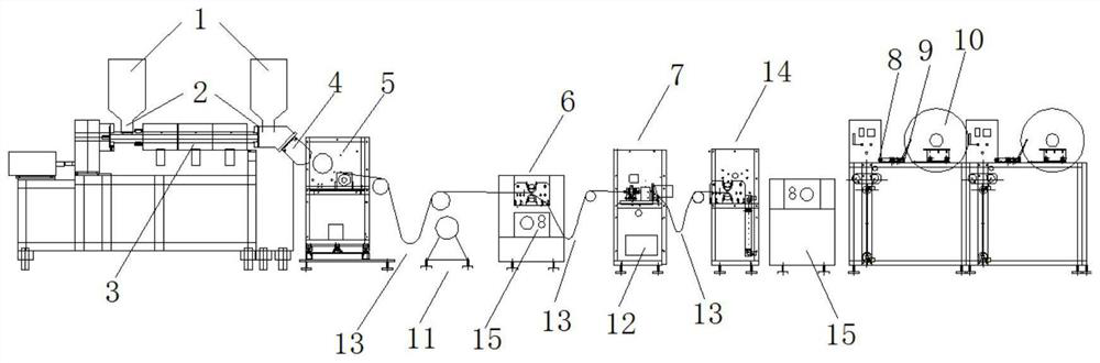
[0069] see Figure 1-14 , the present invention relates to a particle carrier tape forming system and process, the process steps are:

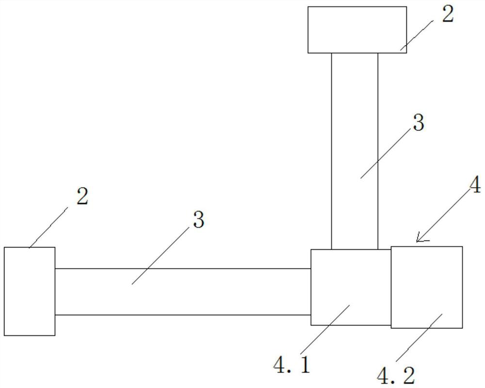
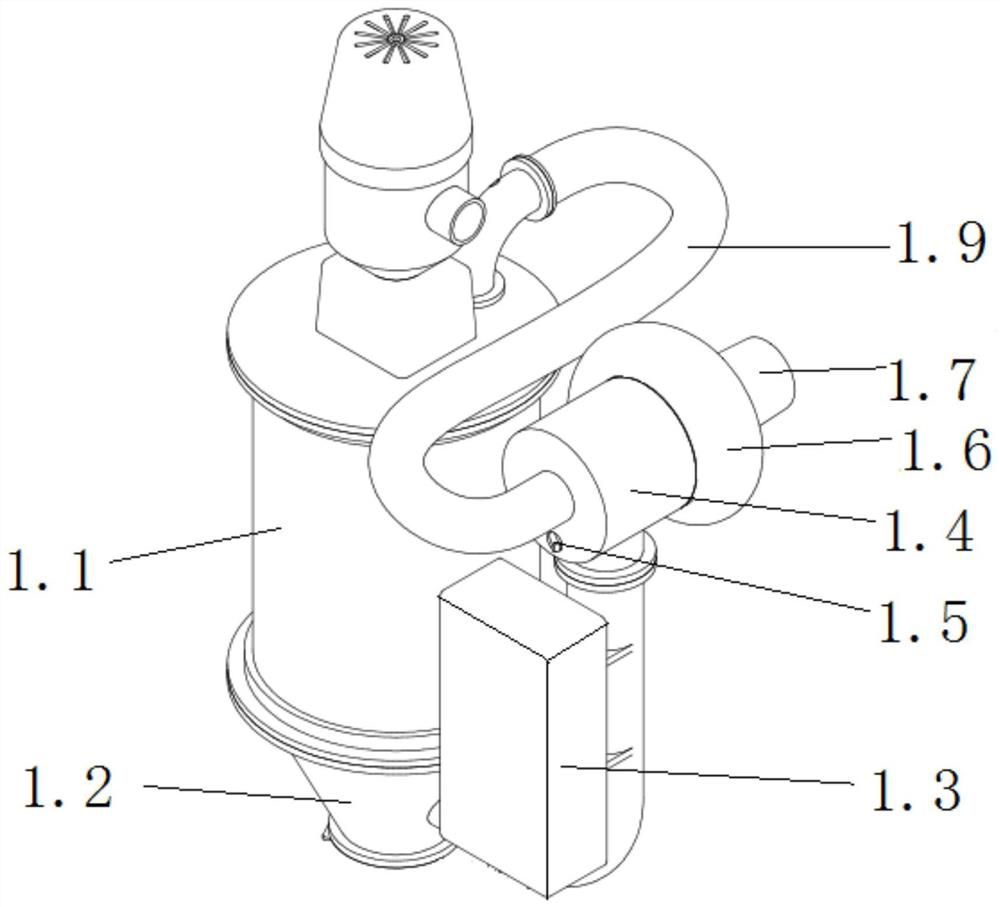
[0070] Step 1, batching: After the master batch A and master batch B are heated and dried by the hot air return system 1, they are input into two screw extruders 3 through two feeding mechanisms 2, and the two screw extruders 3 are respectively Masterbatch A and masterbatch B are extruded into composite extrusion die 4;

[0071] Step 2, forming: the composite extrusion die head 4 laminates the masterbatch A and masterbatch B and transports them to the molding mechanism 5 for molding, that is, the composite extrusion die head 4 presses out the sheet-like carrier tape, and the molding mechanism 5 Continuous vacuum adsorption molding on the carrier tape to form a box cavity;

[0072] Step 3, punching: the punching module 7 punches the carrier tape;

[0073] Step 4, striping: the stripping module 14 strips the carrier tape, and divides the carr...


PUM


Abstract

The invention relate to a particle carrier band forming system and a process. The particle carrier band forming system comprises hot return air systems, a compound extrusion mold head, a forming mechanism, a punching module, a slitting module, a detecting device and a winding mechanism which are arranged in sequence from front to back; two sets of hot return air systems are arranged; material discharging mechanisms are connected with the lower ends of the two sets of hot return air systems respectively; screw rod extruding machines are connected with the material discharging mechanisms respectively; the two screw rod extruding machines are connected with the compound extrusion mold head; a trimming mechanism is arranged on the back side of the forming mechanism; and velocity matching mechanisms are arranged between the forming mechanism and the trimming mechanism, between the trimming mechanism and the punching module, and between the punching module and the slitting module. The particle carrier band forming system and process can save cost and improve production efficiency and product quality.

Description

technical field [0001] The invention relates to a particle carrier tape forming system and process, in particular to a particle carrier tape forming system and process based on a roller vacuum forming method, and belongs to the technical field of carrier tape manufacturing. Background technique [0002] Carrier tape is a belt-shaped structure product used in the field of electronic packaging to hold SMD components. It has a specific thickness and is equidistantly distributed in the length direction of the box cavity for holding electronic components. , Positioning holes located on one side or both sides of the box cavity for index positioning. It is mainly used in the mounting industry of electronic components. It is used with the cover tape to store electronic components such as resistors, capacitors, transistors, and diodes in the box cavity of the carrier tape, and is formed by sealing the cover tape above the carrier tape. Closed packaging is used to protect electronic ...

Claims


Application Information

Patent Timeline
Patent Type & Authority Applications(China)
IPC IPC(8): B29D29/00B29C48/08B29C48/27B29C48/28B29C48/92B29B13/06B65D73/02
CPCB29B13/065B29D29/00B65D73/02B29C48/0022B29C48/08B29C48/27B29C48/28B29C48/92
Inventor 李文仕曾坤灿李劲松李海青潘鹏飞
Owner JIANGYIN WINPACK TECH
Why Eureka
Try Eureka