Diffusion and rectification integrated diffuser

A diffuser and diffuser section technology, which is applied to parts of pumping devices for elastic fluids, machines/engines, liquid fuel engines, etc., can solve problems such as complex manufacturing process, increased assembly difficulty, and large overall size , to achieve the effect of reducing processing difficulty and cost, reducing pressure loss, and reducing overall weight

Pending Publication Date: 2020-09-04
上海尚实航空发动机股份有限公司
View PDF2 Cites 5 Cited by
  • Summary
  • Abstract
  • Description
  • Claims
  • Application Information

AI Technical Summary

Problems solved by technology

However, it has the defects of increased difficulty in assembly, complicated manufacturing process, large overall size and excessive weight

Method used


Image

  • Diffusion and rectification integrated diffuser
  • Diffusion and rectification integrated diffuser
  • Diffusion and rectification integrated diffuser

Examples


Embodiment 1

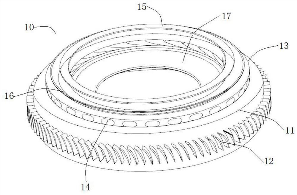
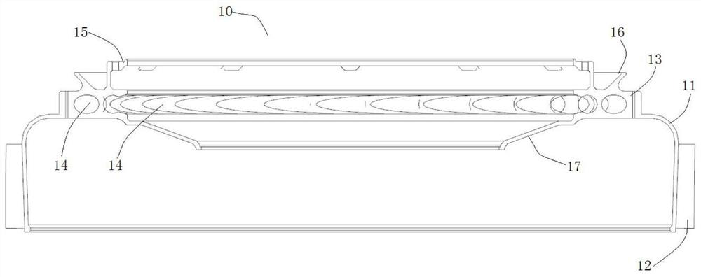
[0033] see figure 1 with figure 2 As shown, the present embodiment provides a diffuser and rectification integrated diffuser, the diffuser 10 is mounted on an aero-engine, including an integrally formed centrifugal compressor disc 11 and coaxially arranged on the centrifugal The radial tubular diffuser section 13 at the top of the compressor wheel 11, wherein: the centrifugal compressor wheel 11 is evenly distributed with a number of rectifying blades 12 in the circumferential direction, and an air flow rectifying channel is formed between two adjacent rectifying blades 12; Along the circumferential direction of the radial tubular diffuser section 13, a number of scattered through holes 14 are opened from the inside to the outside, and the radial angle between the through holes 14 and the radial tubular diffuser section 13 is 20° -30°. The integrated diffuser 10 can effectively reduce the pressure loss caused by the diffusion, improve the working efficiency of the combustio...

Embodiment 2

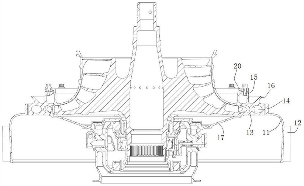
[0038] read on figure 1 with image 3As shown, the difference from the above-mentioned embodiment 1 is that, on the diffuser and rectification integrated diffuser, the top of the radial tubular diffuser section 13 is provided with a connecting flange 15, and the connecting flange 15 The end face is provided with a number of mounting holes, and is connected to the outer casing 20 of the compressor by bolts. Specifically, mounting holes are provided on the connecting flange 15, and bolts and gaskets are used to pass through the outer casing 20 of the compressor to interfere with the corresponding mounting holes, so that the integrated diffuser 10 is fixed on the On the outer casing 20 of the compressor.

[0039] read on image 3 with Figure 4 As shown, a middle connecting plate 16 is arranged on the top of the radial tubular diffuser section 13, and the middle connecting plate 16 is arranged on the outside of the connecting flange 15 in an annular cone structure, and is wel...

Embodiment 3

[0042] Different from the above embodiment 1 and / or embodiment 2, please continue to refer to figure 1 As shown, a number of rectifying blades 12 are evenly distributed on the circumferential edge of the centrifugal compressor disc 11, and an air flow rectifying passage is formed between two adjacent rectifying blades 12, and the shape design of the rectifying blades 12 limits the flow of air flow direction, thereby shortening the overall structural size of the diffuser channel and further improving the working efficiency of the diffuser.

[0043] In this example, see figure 1 with figure 2 As shown, the rectifying blades 12 are deflected counterclockwise by 2-10° along the axial direction of the centrifugal compressor disc 11; The counterclockwise deflection is 3-8°; more preferably, the rectifying blade 12 is deflected 5° counterclockwise along the axial direction of the centrifugal compressor disc 11 . The rectifying vanes 12 are formed by integrated manufacturing and t...


PUM


Abstract

The invention discloses a diffusion and rectification integrated diffuser. The diffusion and rectification integrated diffuser comprises a centrifugal compressor wheel disc and a radial tubular diffusion section which are integrally formed; a plurality of rectification blades are evenly distributed in the circumferential direction of the centrifugal compressor wheel disc, an airflow rectificationchannel is formed between every two adjacent rectification blades; and a plurality of scattered through holes are formed in the circumferential direction of the radial tubular diffusion section from inside to outside, and an radial included angle between each through hole and the radial tubular diffusion section ranges from 20 degrees to 30 degrees. According to the diffusion and rectification integrated diffuser, pressure loss caused by diffusion can be effectively reduced, the working efficiency of a combustion chamber is improved; meanwhile, the shape design of the rectification blades limits the flowing direction of airflow, so that the overall structural size of a diffuser channel is shortened, and the working efficiency is further improved; and due to the integrally formed structuraldesign, the assembly difficulty of diffusion and flow guide is reduced, the overall weight of an engine is reduced, and the fuel economy and the overall performance of the engine are greatly improved.

Description

technical field [0001] The invention relates to the technical field of turboprop engines, in particular to a diffuser and rectification integrated diffuser. Background technique [0002] The compressor, turbine and combustor in the aero-engine are the three core components. Generally, the absolute velocity of the air at the outlet of the aero-engine compressor reaches 120-220m / s. In modern advanced aero-engines, in order to further improve the compressor Boost ratios, airflow velocities are even higher. This part of kinetic energy must be effectively converted into static pressure energy. At the same time, the diversion gas needs to be collected and drawn out. Therefore, a diffuser is added between the compressor and the combustion chamber. The gas drawn out of the diffuser enters the flame tube to help fuel oil to be stable and efficient. Combustion makes the chemical energy of the fuel stably converted into heat energy, drives the turbine to do work, and finally converts ...

Claims


Application Information

Patent Timeline
Patent Type & Authority Applications(China)
IPC IPC(8): F04D29/44
CPCF04D29/441F04D29/444F05D2250/52
Inventor 张礼强陈波高华戴奎王石柱
Owner 上海尚实航空发动机股份有限公司
Why Eureka
Try Eureka