
Adjustable liquid metal antenna array based on magnetic control voltage transformation technology

A liquid metal, antenna array technology, applied in the direction of antenna array, antenna, antenna coupling, etc., can solve the problems of the influence of the array signal, can only be used vertically, and the influence is very huge, to reduce electromagnetic interference, realize automatic control, and can Strong control effect

Pending Publication Date: 2020-09-04
杭州联芳科技有限公司
View PDF1 Cites 0 Cited by
  • Summary
  • Abstract
  • Description
  • Claims
  • Application Information

AI Technical Summary

Problems solved by technology

This invention patent has the following defects: 1. The antenna is directly connected to the liquid metal storage device, that is to say, a large amount of liquid metal in the liquid metal storage tank forms a part of the antenna, which directly affects the shape of the antenna, and then affects the transmission of the antenna. Frequency, when the frequency of the antenna changes, the impact is very huge; 2. The change of the extrusion device causes the change of the shape of the antenna. If only the influence of the antenna length on the transmitted signal is calculated without considering the deformation of the liquid metal in the storage tank, the measurement The results are quite different; 3. The opening above the pipe reduces the application range of the antenna, because it can only be used vertically; 4. The control device other than the antenna has a serious impact on the array signal

Method used


Image

  • Adjustable liquid metal antenna array based on magnetic control voltage transformation technology
  • Adjustable liquid metal antenna array based on magnetic control voltage transformation technology
  • Adjustable liquid metal antenna array based on magnetic control voltage transformation technology

Examples


Embodiment 1

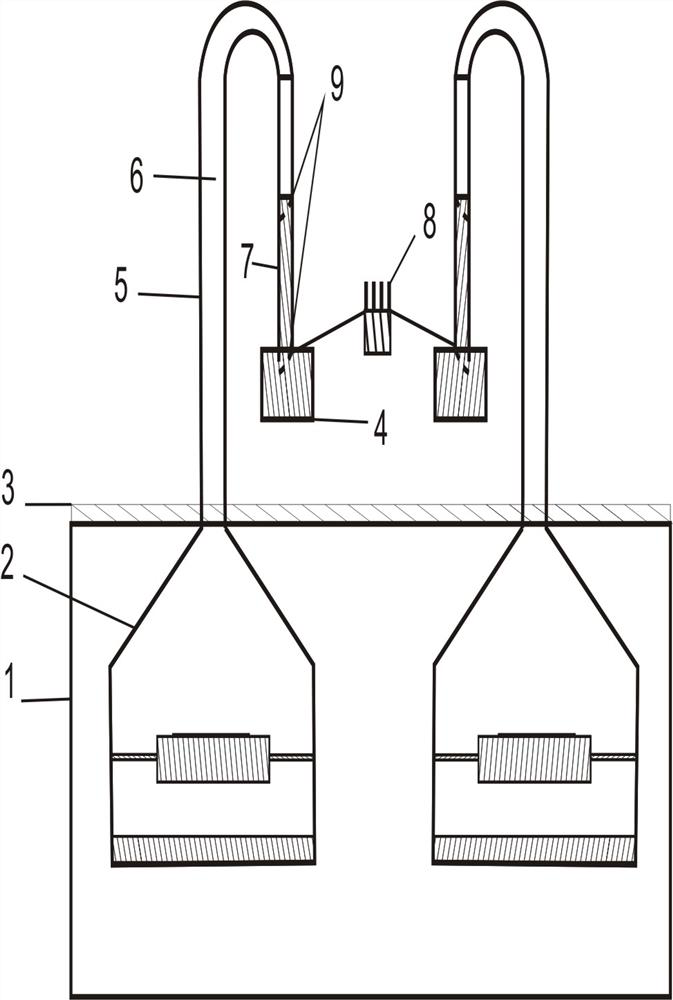
[0027] Such as figure 2 As shown in the schematic diagram of the magnetic control device of the present invention, the magnetic control device 2 comprises an air chamber 2-1, a rubber valve 2-2, an electromagnet 2-3, a magnet 2-4 and a control circuit 2-5, and the magnetic control device 2 passes through the pipeline 5 communicates with the liquid metal antenna, the upper part of the gas chamber 2-1 is encapsulated, and the lower part communicates with the outside world. The rubber valve 2-2 is a film installed in a circular ring, one end is fixed inside the air chamber 2-1, and the other end is fixed on the electromagnet 2-3. The air chamber is filled with inert gas (such as nitrogen), and the inert gas acts as a protection. Liquid metal is not oxidized, by controlling the current in the electromagnet 2-3, the magnetic force between the electromagnet 2-3 and the magnet 2-4 is controlled, and when the electromagnet 2-3 receives the control signal, it goes down ( or upward) m...

Embodiment 2

[0029] Such as image 3 The schematic diagram of the pipeline cut-off valve structure is shown. Calculate the length of the liquid metal antenna according to the required frequency of the antenna, open the pipeline shut-off valve 9 at both ends of the pipeline, start the magnetic control device 2, and use the air pressure change in the pipeline 5 to adjust the liquid metal 7 in the pipeline. After the regulation is over, close the shut-off valves at both ends of the pipeline. The pipeline shut-off valve 9 and the magnetic control device 2 are turned on or off through the control circuit. In order to avoid the influence of the pipeline shut-off valve 9 on the antenna, it is necessary to cut off the liquid metal storage tank 4 in the pipeline. The connection with the liquid metal 7, the cut-off valves 9 at both ends of the pipeline are made of non-conductive materials such as polymers, and the pipeline 5 is made of flexible non-conductive materials. The liquid metal antenna and ...

Embodiment 3

[0031] Such as Figure 4 The workflow diagram of the control module shown is based on the control method of the liquid metal regulated array, including the following steps:

[0032] Calculate the required length of the liquid metal antenna; open the pipeline stop valve 9 through the control circuit 2-5; open the magnetic control device 2, the electromagnet 2-3 attracts the magnet 2-4, and the length of the liquid metal 7 changes under the action of gas pressure , to reach the desired antenna length. Close the magnetic control device 2, close the upper and lower pipeline stop valves 9, and complete the regulation of the liquid metal antenna array. The inert gas effectively prevents the oxidation of the liquid metal 7; the system is highly adjustable and can realize automatic control of large-scale antenna arrays.


PUM

PropertyMeasurementUnit
Resonant frequencyaaaaaaaaaa

Abstract

The invention relates to the technical field of radio communication, in particular to an adjustable liquid metal antenna array based on a magnetic control voltage transformation technology. The liquidmetal antenna array is composed of an independent liquid metal antenna or more than one liquid metal antenna array, a flexible pipeline is filled with the liquid metal, and one end of the pipeline isconnected with a liquid metal storage tank; a controllable pipeline stop valve is used for executing the connection and disconnection operation, the other end of the pipeline is connected with a magnetic control device, and the controllable pipeline stop valve is used for executing the connection and disconnection operation in the middle. The beneficial effects are that the influence of the liquid metal storage tank on the antenna is effectively eliminated; a control area and an application area are divided by using an isolation plate, so that the electromagnetic interference is effectively reduced; the controllability of the magnetic control device is high, and the array frequency can be continuously changed in a short time; an inert gas effectively prevents the liquid metal from being oxidized; the system is high in controllability, and can achieve the automatic control of a large-scale antenna array.

Description

technical field [0001] The invention relates to the technical field of radio communication, in particular to an adjustable liquid metal antenna array based on magnetron voltage transformation technology. Background technique [0002] With the rapid development of science and technology, wireless communication technology has become an indispensable part of people's daily life. PDMS-based flexible liquid metal antennas rely on the "reconfigurable", "self-healing" and "heat expansion The nature of "shrink" and so on has been paid more and more attention in the field of antennas, so it has a better market prospect and an optimistic development prospect. Liquid metal antenna technology has many advantages over traditional solid-state antenna technology, so the products output using liquid metal antenna technology will have an overwhelming advantage in the market and can quickly occupy the market, and the replaced old technology will no longer have a market. [0003] The advantag...

Claims


Application Information

Patent Timeline
IPC IPC(8): H01Q1/36H01Q1/52H01Q3/01H01Q5/10H01Q21/00F16K31/06
CPCF16K31/0672H01Q1/364H01Q1/526H01Q3/01H01Q21/00H01Q5/10
Inventor 卢斌张之涵汤丰杰苏成欢刘雨萱乔宪武李祥
Owner 杭州联芳科技有限公司
Learn More