Eureka AIR delivers breakthrough ideas for toughest innovation challenges, trusted by R&D personnel around the world.

Acousto-optical device and method

A technology of acousto-optic components and acousto-optic modulators, which is applied in the field of light dispersion angle, optical microscope, and dispersion angle devices, and can solve problems such as expensive, poor resolution, and reduced effects

Pending Publication Date: 2020-09-04
LEICA MICROSYSTEMS CMS GMBH
View PDF16 Cites 1 Cited by
  • Summary
  • Abstract
  • Description
  • Claims
  • Application Information

AI Technical Summary

Problems solved by technology

[0019] For applications in (multiphoton) microscopy, too large a CSA is problematic for two reasons: firstly, the different propagation directions of the colored components of the femtosecond light pulse are responsible for making The beam profile is elliptical and thus does not illuminate the entrance pupil of the excitation objective optimally, which in particular leads to poorer resolution or reduced effectiveness (when the entrance pupil is over-illuminated)
But these schemes are either quite expensive or inflexible (e.g. when the laser wavelength is changed)

Method used


Image

  • Acousto-optical device and method
  • Acousto-optical device and method
  • Acousto-optical device and method

Examples


Embodiment Construction

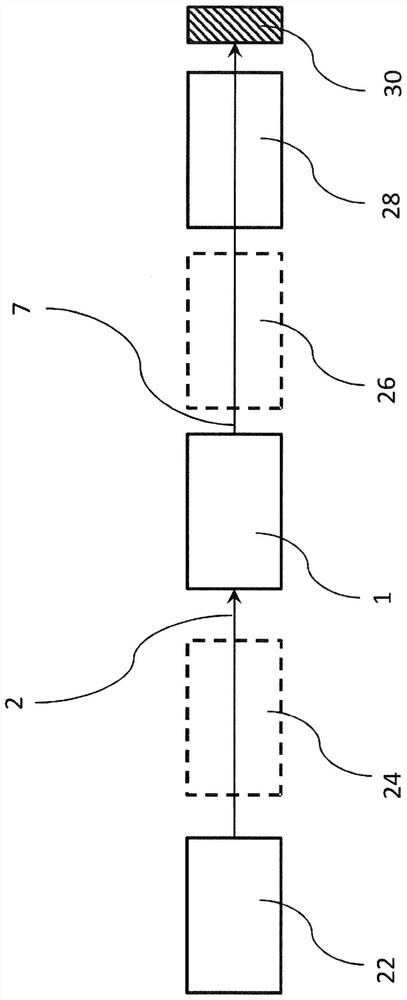
[0043] figure 1 The usual beam path of a scanning microscope, for example a multiphoton microscope, with an acousto-optic element 1 , in particular an AOM, as beam modulator is shown in extremely simplified form. An incident light beam 2 reaches the acousto-optic element 1 from a light source 22 , such as a laser, in particular a pulsed laser, optionally through beam guiding and conditioning optics 24 . From there, the light 7 diffracted on the acousto-optic element 1 passes through optional imaging and scanning optics 26 to the objective 28 and finally to the sample 30 .

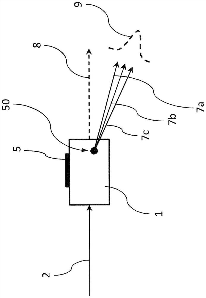
[0044] figure 2 Schematically shows the diffraction process on an AOM 1 illuminated by an incident light beam 2 with a given central wavelength λ and spectral width Δλ. On the crystal of AOM 1 is mounted a transducer 5 which applies radio frequency (RF) into the crystal. The diffraction orders ±1 of the diffracted light 7 , which are usually used as useful light beams, are produced at the resulting grat...


PUM


Abstract

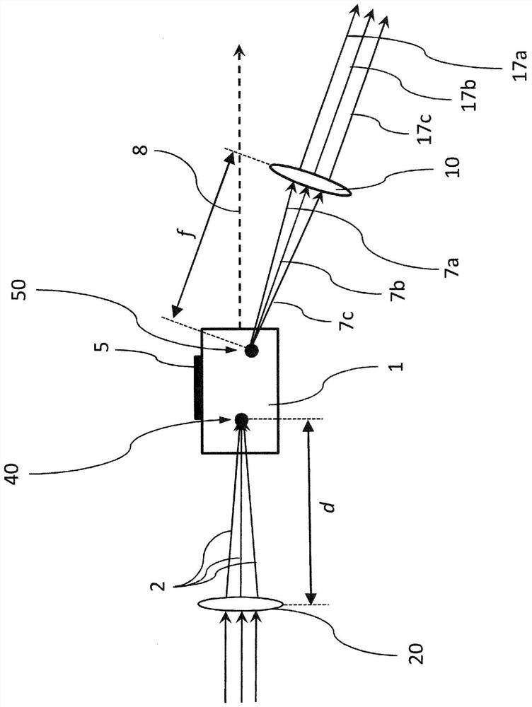
The invention relates to a device for reducing the chromatic spread angle of light (7) diffracted by an acousto-optical element (1), said device comprising an acousto-optical element (1), arranged ina beam path of an incident light beam (2), which produces the diffracted light from the incident light beam (2) that starts from a virtual interaction point (50) of the acousto-optical element (1), characterised in that the device comprises two focusing optics (10, 20), the first focusing optics (20) being arranged in the beam path upstream of the acousto-optical element (1) and the second focusing optics (10) being arranged in the diffracted light (7), and a focus (40) of the incident light beam (2) being located downstream of the first focusing optics (20) in the acousto-optical element (1),and the virtual interaction point (50) being in the front focal point of the second focusing optics (10).

Description

technical field [0001] The present invention relates to the field of optical microscopy, in particular multiphoton microscopy. [0002] The invention relates to a device for reducing the dispersion angle of light diffracted on an acousto-optic element, comprising an acousto-optic element and two focusing optics. The invention also relates to a method for reducing the dispersion angle of light diffracted on an acousto-optic element. Background technique [0003] In many areas of optical microscopy, regardless of the method used, a major requirement is the provision of excitation light at one or more defined wavelengths. Depending on the microscopic method and / or sample type, one or more excitation beams may be required, which usually must have defined spectral properties. [0004] For example, in the field of fluorescence microscopy it is important to use light with a wavelength which excites fluorescence. Especially when the sample contains fluorescent substances with dif...

Claims


Application Information

Patent Timeline
IPC IPC(8): G02B21/00G01J3/12G02F1/11
CPCG02F1/11G02B21/0032G02B21/0064G02B21/0076G02B21/0036G02F1/116G02F1/33
Inventor 曼努埃尔·克雷默菲利克斯·纽加特
Owner LEICA MICROSYSTEMS CMS GMBH
Why Eureka
Eureka Blog
Learn More