Full-automatic servo straight edge sealing machine

An edge banding machine, fully automatic technology, used in multi-purpose machinery, forming/shaping machines, special forming/shaping machines, etc., can solve the problems of low degree of automation, danger, slow speed, etc. The effect of high degree of automation and improved machining accuracy

Pending Publication Date: 2020-09-08
东莞市繁茂木工机械设备有限公司
View PDF0 Cites 8 Cited by
  • Summary
  • Abstract
  • Description
  • Claims
  • Application Information

AI Technical Summary

Problems solved by technology

The existing edge banding machine, according to the thickness of the edge band, needs to be manually adjusted by manually turning the knob on the screw pair to adjust the distance between the front and back of the milling cutter, thereby changing the contact depth between the wood and the cutter, but due to the manual adjustment of the screw pair The error is large, and the staff needs to be close to the equipment to read the value of the scale, which is dangerous, and it needs to be shut down during adjustment, with low degree of automation and low work efficiency
Moreover, the working efficiency of some mechanisms of the existing edge banding machine is low, which slows down the overall speed
For example, the two groups of cutters in the head-to-head mechanism are set on the same track together. After the first group of cutters completes the process, it is necessary to wait for the second group to be completed before the first group can be reset, which wastes time; also, in the tracking mechanism The cutting tool is directly exposed on the outside of the motor. When the wood comes in, it directly contacts the wood. When the speed of the conveyor belt is too high, the wood will directly collide with the knife and cause a gap, making the product scrapped. In order to avoid this situation, we can only Reduce the speed of the conveyor belt and reduce the overall efficiency

Method used


Image

  • Full-automatic servo straight edge sealing machine
  • Full-automatic servo straight edge sealing machine
  • Full-automatic servo straight edge sealing machine

Examples


Embodiment Construction

[0041] In order to make the above objects, features and advantages of the present invention more comprehensible, specific implementations of the present invention will be described in detail below in conjunction with the accompanying drawings. It should be noted that all the drawings of the present invention are in simplified form and use imprecise ratios, which are only used to facilitate and clearly assist the purpose of illustrating the embodiments of the present invention.

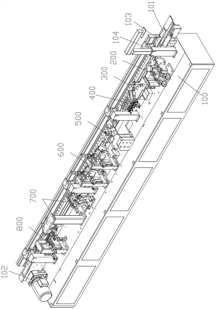
[0042] Such as figure 1 As shown, it includes a workbench 100, a conveyor belt arranged on the workbench, and a PLC control system, and the conveyor belt is used to transport wood; the conveyor belt is driven by a conveyor belt 101 and connected to the conveyor belt. The motor 102 and the uniform array are composed of several conveying rollers 103 correspondingly arranged on the top of the conveyor belt. On the side of the conveyor belt, several groups of pneumatic pressure plates 104 are also provided...


PUM


Abstract

The invention discloses a full-automatic servo straight edge sealing machine. The full-automatic servo straight edge sealing machine comprises a workbench, a conveying belt and a PLC control system; and the conveying belt is used for conveying wood. and full-automatic servo straight edge sealing machine also comprises a side belt feeding mechanism, a straight edge press-fitting mechanism, a double-track side belt trimming mechanism, an up-and-down finishing mechanism, an up-and-down tracking mechanism and an up-and-down scraper mechanism which are arranged beside the conveying belt in sequence; a thickness identification assembly electrically connected with the PLC control system is arranged on the side belt feeding mechanism, and is used for acquiring the thickness of a side belt; the up-and-down finishing mechanism comprises a finishing knife module; the up-down tracking mechanism comprises a tracking milling cutter module; the up-and-down scraper mechanism comprises a scraper module; and the finishing cutter module, the tracking milling cutter module and the scraper module are electrically connected with the PLC control system. Cutters in the modules above can be automatically adjusted according to data obtained by the PLC control system from the thickness identification assembly without shutting down to control manually, processing parameters of side belts in different thicknesses are adapted, and the full-automatic servo straight edge sealing machine has the advantages of high automation degree, high processing precision and high working efficiency.

Description

technical field [0001] The invention relates to the technical field of edge banding machines, in particular to a fully automatic servo straight edge banding machine. Background technique [0002] The edge banding machine is a kind of equipment that replaces the manual sealing of the edge band on the wood, which includes conveying, gluing and wetting, cutting, front and rear alignment, up and down trimming, up and down fine trimming, up and down tracking, polishing, etc. Features. The existing edge banding machine, according to the thickness of the edge band, needs to be manually adjusted by manually turning the knob on the screw pair to adjust the distance between the front and back of the milling cutter, thereby changing the contact depth between the wood and the cutter, but due to the manual adjustment of the screw pair The error is large, and the staff needs to be close to the equipment to read the value of the scale, which is relatively dangerous, and it needs to be sto...

Claims


Application Information

Patent Timeline
Patent Type & Authority Applications(China)
IPC IPC(8): B27M1/08B27C9/04B27C5/00B27C5/02B27C5/06B27D5/00B27N7/00B26D1/10B26D5/12
CPCB26D1/105B26D5/12B27C5/006B27C5/02B27C5/06B27C9/04B27D5/003B27D5/006B27M1/08B27N7/00
Inventor 李满树
Owner 东莞市繁茂木工机械设备有限公司
Why Eureka
Try Eureka