Automatic blow molding system based on raw material processing

A raw material processing and automatic blow molding technology, which is applied to the separation of dispersed particles, chemical instruments and methods, separation methods, etc., can solve problems such as air leakage, prolonged blow molding time, and affecting blow molding efficiency and effect, etc., to achieve Safe and convenient to use, increase efficiency and improve blow molding effect

Inactive Publication Date: 2020-09-08
张周钦
View PDF6 Cites 3 Cited by
  • Summary
  • Abstract
  • Description
  • Claims
  • Application Information

AI Technical Summary

Problems solved by technology

[0003] At present, when the existing automatic blow molding machines on the market are used, when the tubular plastic parison is blown, because there are gaps between the tubular plastic parison molds, it is easy to cause the air passing into the tubular plastic parison to leak out, resulting in blow molding. The time required is prolonged, which affects the efficiency and effect of blow molding production

Method used


Image

  • Automatic blow molding system based on raw material processing
  • Automatic blow molding system based on raw material processing
  • Automatic blow molding system based on raw material processing

Examples


Embodiment Construction

[0041] The preferred embodiments of the present invention will be described below in conjunction with the accompanying drawings. It should be understood that the preferred embodiments described here are only used to illustrate and explain the present invention, and are not intended to limit the present invention.

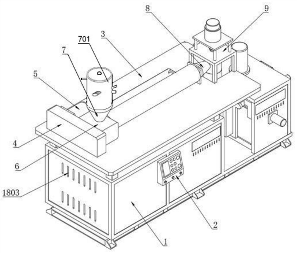
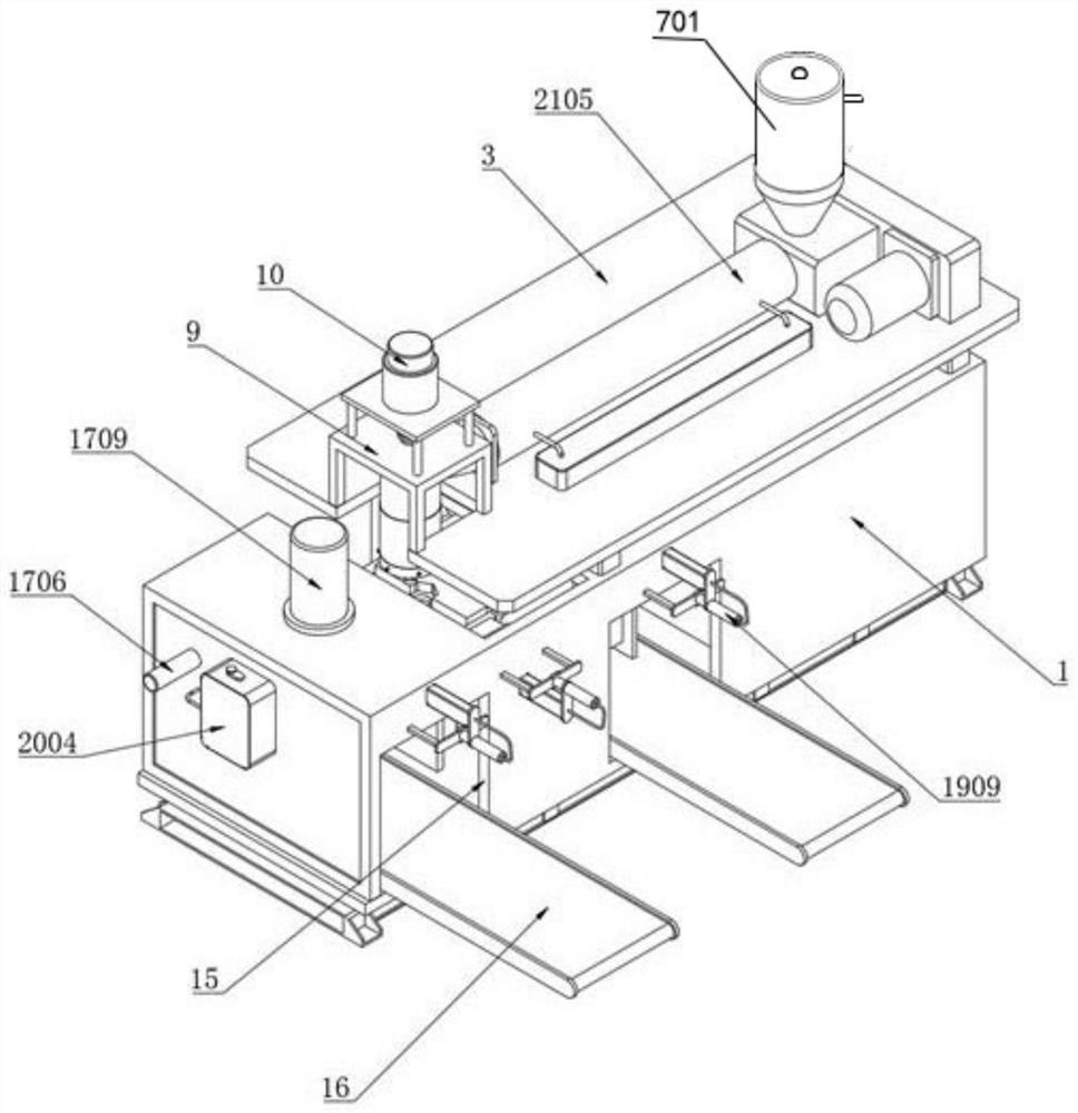
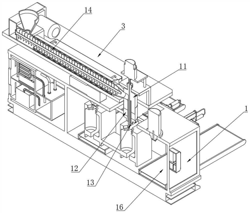
[0042] Example: such as figure 1 , 16-18 shows an automatic blow molding system based on raw material processing, including a blow molding machine box 1, a control switch 2 is installed at one end of the blow molding machine box 1, and a top plate is installed at the top of the blow molding machine box 1 through a connecting column 3. The top of the top plate 3 is fixedly connected with the transmission chamber 4, the top of the top plate 3 is connected with the injection motor 5 at the position corresponding to the end of the transmission chamber 4, and the one end of the transmission chamber 4 is installed at the position corresponding to the side of the injection...


PUM


Abstract

The invention discloses an automatic blow molding system based on raw material processing, wherein the upper end of a feeding cabin communicates with a raw material processing shell; a round plate isdisposed inside the raw material processing shell with an end cap; the round plate is fixedly connected to a rotation motor by an output shaft of the rotation motor; the upper end of the round plate is fixedly connected to an annular protective wall; a stirring motor is fixedly embedded in the center of the round plate; an output shaft of a stirring motor is fixedly connected to a stirring rod; aninfrared receiver is fixedly embedded on the side wall of one end of the round plate; the infrared receiver is used for receiving signals of an infrared emitter which is embedded fixedly on the innerwall of the raw material processing shell; the other end of the round plate is equipped with an insertion hole; the insertion hole is used for insertion of an output rod of an electric telescopic rod; a shell of the electric telescopic rod is fixedly connected to the raw material processing shell; and one side of the raw material processing shell communicates with a hot wind inlet pipe, the otherside of the raw material processing shell communicates with a gas lack exhaust pipe, and the bottom end of the round plate is fixedly connected to a weight sensor and a single-chip microcomputer controller.

Description

technical field [0001] The invention relates to the technical field of automatic blow molding, in particular to an automatic blow molding system based on raw material processing. Background technique [0002] The blow molding machine is a kind of plastic processing machine. The tubular plastic parison obtained by extrusion or injection molding of thermoplastic resin is placed in the split mold while it is hot. After the mold is closed, compressed air is injected into the parison to make the plastic The parison is inflated and clings to the inner wall of the mold, and after cooling and demoulding, various hollow products can be obtained; [0003] At present, when the existing automatic blow molding machines on the market are used, when the tubular plastic parison is blown, because there are gaps between the tubular plastic parison molds, it is easy to cause the air passing into the tubular plastic parison to leak out, resulting in blow molding. The time required is prolonged...

Claims


Application Information

Patent Timeline
Patent Type & Authority Applications(China)
IPC IPC(8): B29C49/06B29C49/28B29C49/30B29C49/42B29C49/48B29C49/50B29C49/78B29B13/00B29B13/02B29B13/06B29C33/70B01D53/26B01D53/18
CPCB29C49/06B29C49/28B29C49/30B29C49/42B29C49/4205B29C49/4252B29C49/4278B29C49/4284B29C49/48B29C49/50B29C49/78B29B13/00B29B13/022B29B13/06B29C33/70B01D53/26B01D53/18B29C2049/4294B29C2049/023
Inventor 张周钦
Owner 张周钦
Why Eureka
Try Eureka