
Chemical waste liquid heavy metal residue treatment equipment

A technology for treating equipment and heavy metals, applied in sludge treatment, sedimentation treatment, water/sewage treatment, etc., can solve the problems of poor equipment treatment effect, low water output, poor effect, etc., achieve good treatment effect, increase water output, Effect of improving mixing efficiency

Inactive Publication Date: 2020-09-08
广州道源信息科技有限公司
View PDF0 Cites 4 Cited by
  • Summary
  • Abstract
  • Description
  • Claims
  • Application Information

AI Technical Summary

Problems solved by technology

[0005] Aiming at the deficiencies of the prior art, the present invention provides a chemical waste liquid heavy metal residue treatment equipment, which solves the problem that the currently used heavy metal treatment equipment cannot quickly mix heavy metals and additives evenly during the process of mixing waste liquid. , which reduces the mixing efficiency of heavy metals. The precipitation operation of heavy ions is not in place at present. It cannot ensure the rapid standing of the liquid under the condition of ensuring a good mixing degree, so that the sediment cannot be quickly settled. Now adding agents to clarify The effect of the treatment is poor, and the treatment speed of the clarification treatment cannot be made faster, which reduces the treatment efficiency of the metal ion treatment device. Moreover, the cleaning and filtration of the wastewater in the current heavy metal sewage treatment process leads to incomplete separation of heavy metal ions, and the water output after wastewater treatment is relatively high. less, it cannot guarantee long-term continuous operation, and it is easy to cause the problem of poor processing effect of the equipment

Method used


Image

  • Chemical waste liquid heavy metal residue treatment equipment
  • Chemical waste liquid heavy metal residue treatment equipment
  • Chemical waste liquid heavy metal residue treatment equipment

Examples


Embodiment Construction

[0031] The following will clearly and completely describe the technical solutions in the embodiments of the present invention with reference to the accompanying drawings in the embodiments of the present invention. Obviously, the described embodiments are only some, not all, embodiments of the present invention. Based on the embodiments of the present invention, all other embodiments obtained by persons of ordinary skill in the art without making creative efforts belong to the protection scope of the present invention.

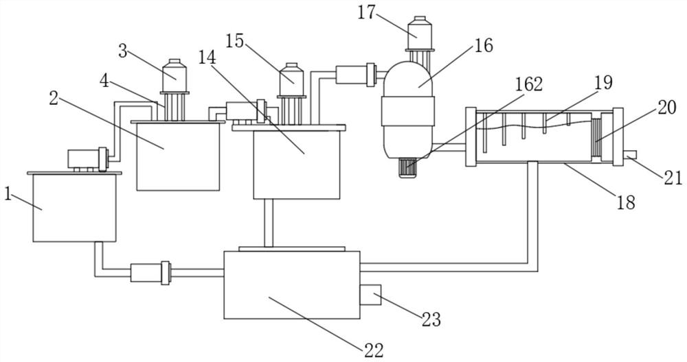
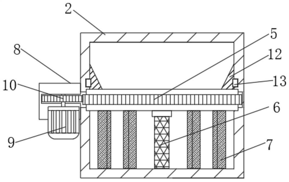
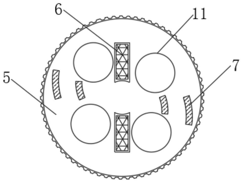
[0032] see Figure 1-6 , a chemical waste liquid heavy metal residue treatment equipment, including a heavy metal waste tank 1, a neutralization tank 2, a settling tank 14, a flocculation tank 16 and a clarification separation tank 18, the top of the heavy metal waste tank 1 is connected to the neutralization tank through a pipeline In 2, the first dosing device 3 is arranged above the neutralization box 2, the middle part of the neutralization box 2 is rotata...


PUM


Abstract

The invention relates to the technical field of heavy metal treatment. The invention discloses chemical waste liquid heavy metal residue treatment equipment. The equipment comprises a heavy metal waste liquid tank, a neutralization tank, a settling tank, a flocculation tank and a clarification separation tank, wherein the top end of the heavy metal waste liquid tank is connected into the neutralization tank through a pipeline, a first dosing device is arranged above the neutralization tank, a gear disc is rotatably connected to the middle of the neutralization tank, a rotating plate and a water shoveling mixing plate are fixedly mounted at the bottom end of the gear disc, and a plurality of notches are formed in the middle of the gear disc. According to the chemical waste liquid heavy metal residue treatment equipment, at present, heavy metal ions are completely separated in the heavy metal sewage treatment process, long-term continuous operation can be guaranteed, the treatment effectof the device is good, it is guaranteed that heavy metal and added chemicals can be rapidly and evenly mixed, it is guaranteed that a liquid can rapidly reach the standing state, sediment can be rapidly subjected to sedimentation treatment, and the treatment efficiency of the metal ion treatment device is improved.

Description

technical field [0001] The invention relates to the technical field of heavy metal treatment, in particular to equipment for treating heavy metal residues in chemical waste liquid. Background technique [0002] The original meaning of heavy metals refers to metals with a density greater than 4.5g / cm3, including gold, silver, copper, iron, mercury, lead, cadmium, etc. Heavy metals accumulate in the human body to a certain extent and can cause chronic poisoning. However, in terms of environmental pollution, heavy metals mainly refer to heavy elements with significant biological toxicity such as mercury (mercury), cadmium, lead, chromium, and metalloid arsenic. Heavy metals are very difficult to be biodegraded. On the contrary, they can be enriched by hundreds of times under the biomagnification of the food chain, and finally enter the human body. Heavy metals can strongly interact with proteins and enzymes in the human body, making them inactive, and may also accumulate in ce...

Claims


Application Information

Patent Timeline
IPC IPC(8): C02F9/04C02F11/122C02F101/20
CPCC02F1/5236C02F1/66C02F9/00C02F11/122C02F2001/007C02F2101/20
Inventor 翁丹丽
Owner 广州道源信息科技有限公司
Learn More