Supercharge Your Innovation With Domain-Expert AI Agents!

Mass center position detection method of space rigid body based on fusion of vision and inertial unit

A technology of inertial unit and detection method, which is applied in the testing of machines/structural components, static/dynamic balance testing, measuring devices, etc., can solve problems such as poor adaptability and difficulty in identifying feature points, and achieve high accuracy and improve robustness. Rodness, high measurement effect

Active Publication Date: 2021-05-28
HEBEI UNIV OF TECH
View PDF9 Cites 0 Cited by
  • Summary
  • Abstract
  • Description
  • Claims
  • Application Information

AI Technical Summary

Problems solved by technology

[0004] Xie Tangtao from the School of Aerospace and Materials Engineering, National University of Defense Technology, and others proposed a method for identifying the centroid of space non-cooperative targets based on visual feature points. This method calculates the velocity information of feature points by visually measuring and matching feature points on space targets. And position information, and then bring it into the space rigid body velocity equation to solve, it can achieve better accuracy under good lighting conditions, but only using visual methods to measure is easily interfered by space stray light, under lighting conditions In the case of too bright or too dark, the identification of feature points is extremely difficult, so the adaptability of this method is poor

Method used


Image

  • Mass center position detection method of space rigid body based on fusion of vision and inertial unit
  • Mass center position detection method of space rigid body based on fusion of vision and inertial unit
  • Mass center position detection method of space rigid body based on fusion of vision and inertial unit

Examples


Embodiment Construction

[0052]A specific embodiment of the present invention is given below. DETAILED DESCRIPTION OF THE INVENTION The present invention is intended to be described in further detail without limiting the scope of the claims.

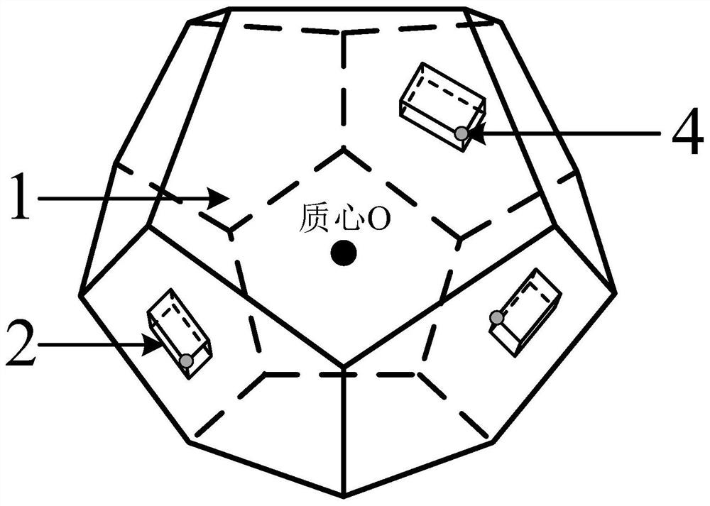
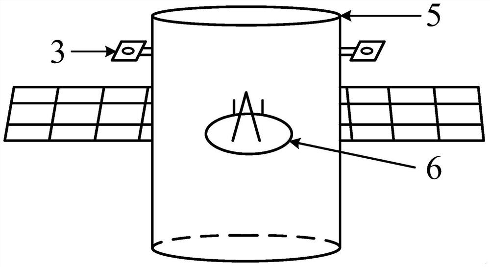
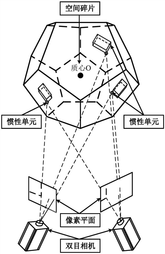
[0053]In response to the active removal of spatial debris, the centroid change of non-cooperative targets such as spatial debris, and the cooperative target of the spinning device satellite is proposed for the satellite centroid change in the process of robotic arm. The detection method of the physical center position can ensure the accuracy of the removal device for the selection of spatial debris, and the stability of the hierarchy device, ensuring the correct implementation and space of the removal device during the flyer. Accurate identification of fragmentation.

[0054]The present invention provides a spatial rigid centroid position detection equipment based on visual and inertial unit fuses comprising a multi-inertial unit measuring system, a visual positioning syste...


PUM


Abstract

The invention is a method for detecting the position of the center of mass of a rigid body in space based on fusion of vision and inertial units. In this detection method, a plurality of inertial units with light sources are arranged on the space rigid body to be detected, including a center of mass calculation module, and the position h of the light source of the inertial unit is k is the center of the sphere, the distance r from the position of the inertial unit light source to the center of mass of the rigid body in space k Create multiple radius measurement spheres for radius O k ; Through the correlation principle of the least squares method, utilize the multiple radii that have been established to measure the ball O k , find a point Q in the space i The sum of the distances from each spherical surface is the shortest, and the coordinates of this point are taken as the position of the centroid point measured at time i; the position of the centroid at multiple times is continuously calculated, the position of the centroid at multiple times is fused, and the position of the center of mass is continuously corrected. When the error of the position of the centroid at two moments is less than 5 %, the position of the center of mass is regarded as the exact position. The method is designed for the centroid detection of space rigid body. The method combines visual and inertial units to complement each other's advantages and improve the robustness of the method.

Description

Technical field[0001]The present invention relates to the field of spatial rigidity core measurement technology, and is specifically a method for detecting a spatial rigidity.Background technique[0002]Since the 1950s, the Soviet Union launched the world's first artificial satellite "Spaternik No. 1", human beings have conducted thousands of spacecraft launches, and each track around the earth has been millions of space rigid body. Cover, in order to determine the kinetic data of the spatial rigid body, the catholic data of the spatial rigid body needs to be determined. In addition to the number, the size of the number, the dimensional, the end of the collision derivative, which has a large amount of space fragments, such as the number, the failure satellite, rocket, and collision derivatives, etc., especially. In March 2019, India conducted the first anti-satellite experiment of the country. It used a three-level missile to hit the Indian military satellite MSI - R, and produced hun...

Claims


Application Information

Patent Timeline
Patent Type & Authority Patents(China)
IPC IPC(8): G06T7/70G01M1/12G06F17/11
CPCG01M1/122G06F17/11G06T7/70
Inventor 张慧博姚金铭赵宝山张跃戴士杰
Owner HEBEI UNIV OF TECH
Features
  • R&D
  • Intellectual Property
  • Life Sciences
  • Materials
  • Tech Scout
  • Unparalleled Data Quality
  • Higher Quality Content
  • 60% Fewer Hallucinations
Learn More