Fluid control device and fluid control method

A control method and fluid manipulation technology, applied in chemical instruments and methods, laboratory utensils, laboratory containers, etc., can solve the problems of aerosol pollution, increase system volume and cost, difficulty in quantifying trace fluids, etc., and achieve simplification Operation, avoid contaminant leakage, solve the effect of quantitative difficulties

Active Publication Date: 2020-09-11
HANGZHOU ZIJING BIOLOGY CO LTD
View PDF5 Cites 13 Cited by
  • Summary
  • Abstract
  • Description
  • Claims
  • Application Information

AI Technical Summary

Problems solved by technology

[0003] Compared with traditional experimental operations using pipette guns and centrifuge tubes, microfluidic chips have advantages in integration and automation, but limited by fluid control methods, microfluidic chips also face the following problems: (1) The fluid control method is complicated, and the fluid control on the microfluidic chip often requires external air pressure sources such as syringe pumps and air pumps, or the use of centrifuges to provide fluid driving force, which greatly increases the volume and cost of the entire system; or use surface modification, Fluid self-driving is achieved by means of capillary force, etc., but at the same time it also leads to insufficient stability, which limits the application scenarios of microfluidic systems; (2) It is difficult to quantify microfluidics, and many steps in biochemical analysis experiments need to be accurately drawn with a pipette Microliter-level liquids are used for reaction system configuration, etc., but this step is difficult to implement on a microfluidic chip, often requiring the design of complex valve structures, or sacrificing the accuracy of the entire system; (3) Fluid mixing issues, biochemical The reaction process involves multi-step liquid mixing steps, which causes more difficulties for the design of microfluidic chips; (4) the problem of system closure, the biochemical reaction process needs to be carried out in a centrifuge tube, taking nucleic acid amplification as an example, due to the During the amplification process, it needs to be heated and amplified exponentially, which is prone to aerosol pollution and may lead to false positives; therefore, the internal fluid space of the microfluidic chip needs to be fully enclosed, and at the same time, the interface between the chip and the outside world to achieve fluid control should be taken into account.

Method used


Image

  • Fluid control device and fluid control method
  • Fluid control device and fluid control method
  • Fluid control device and fluid control method

Examples


Embodiment 1

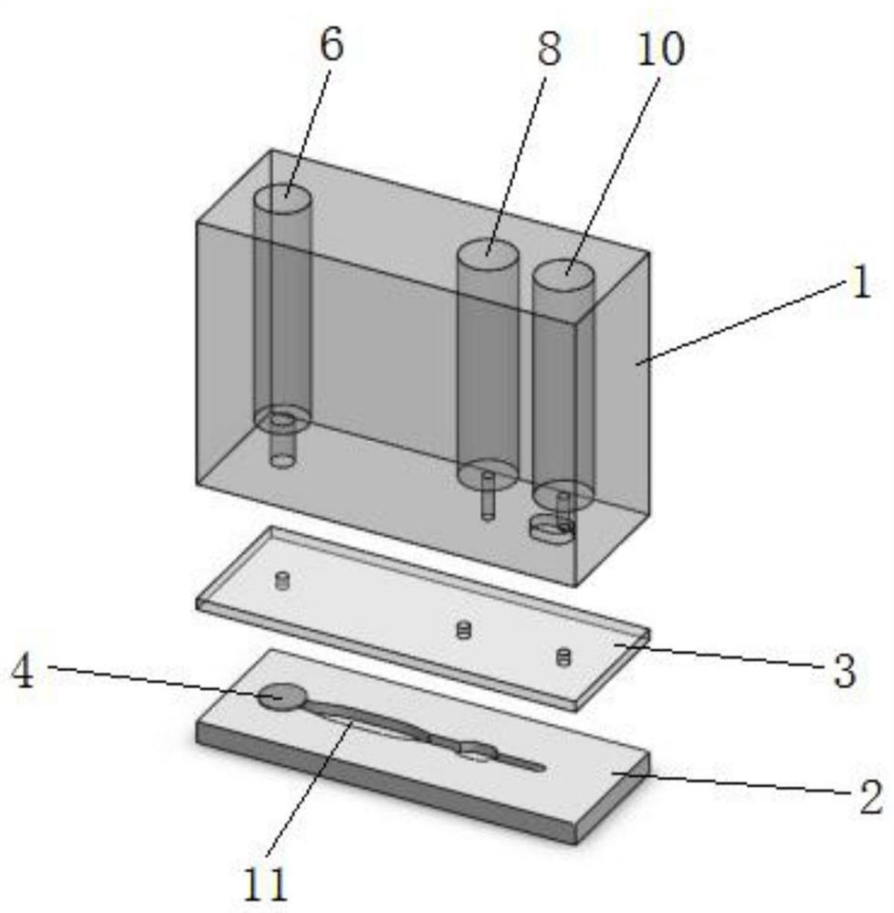
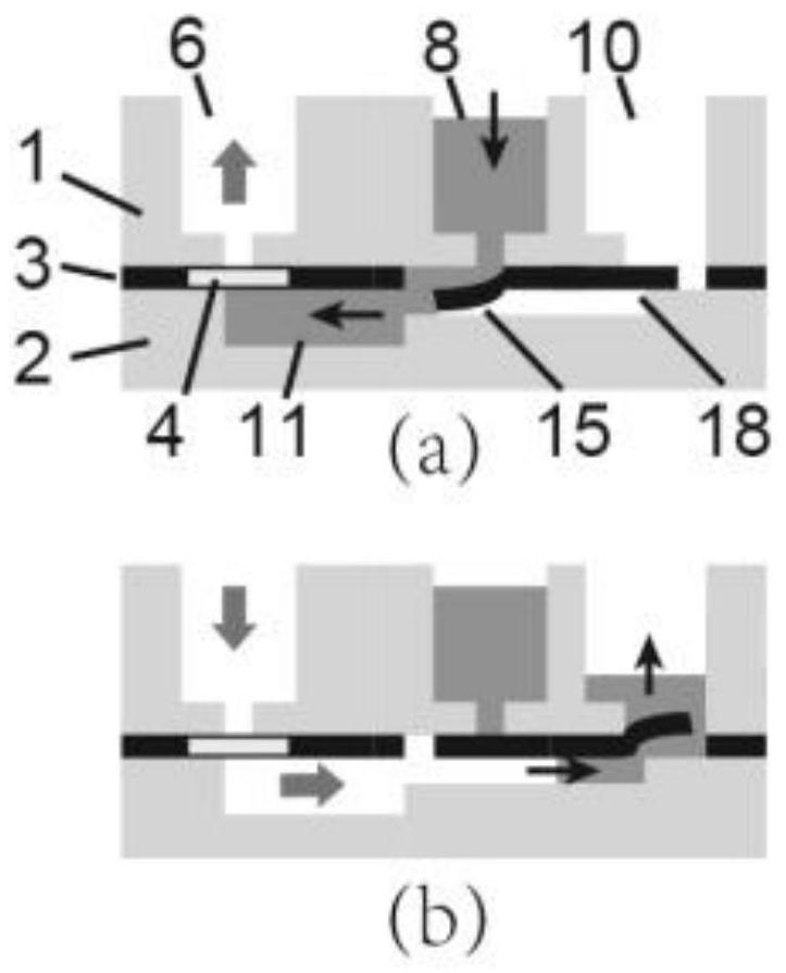
[0030] figure 1 , figure 2 The fluid manipulation device that can realize the quantitative function of microfluid provided according to the first embodiment of the present invention is shown. The fluid manipulation device includes: a cartridge 1, on which a control chamber 6, a reagent chamber 8 and a recovery chamber 10 are formed, and The bottom of the control chamber 6 , the reagent chamber 8 and the recovery chamber 10 are all formed with an opening; the lower chip 2 is formed with a quantitative pool 11 ; the elastic film 3 is used to bond the lower chip 2 to the cartridge 1 The bottom, and the elastic film 3 is provided with the same number of through holes as the bottom openings of the cartridge 1, wherein the opening of the control chamber 6 coincides with the through holes on the elastic film 3, so that the control chamber 6 is communicated with the quantitative pool 11. ; The openings of the reagent chamber 8 and the recovery chamber 10 do not overlap with the thro...

Embodiment 2

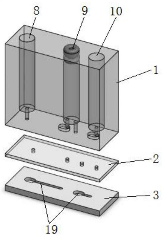
[0037] image 3 , Figure 4 The fluid manipulation device that can realize the one-step fluid mixing and transfer function provided according to the second embodiment of the present invention is shown. The fluid manipulation device includes: a cartridge 1, on which a reagent chamber 8, a mixing chamber 9 and a recovery chamber are formed. chamber 10, and the bottom of the reagent chamber 8 and the recovery chamber 10 is formed with an opening, the mixing chamber 9 is a closed chamber and its bottom is formed with an inlet and an outlet; the lower chip 2 is formed with at least two Disconnected fluid pipeline 19; elastic membrane 3, used to bond the lower chip 2 on the bottom of the cartridge 1, the elastic membrane 3 is provided with the same number of through holes as the bottom opening of the cartridge 1, and the reagent chambers 8, The mixing chamber 9 and the recovery chamber 10 do not coincide with the through holes on the elastic membrane 3, so that between the opening ...


PUM


Abstract

The invention relates to a fluid control device and a fluid control method for realizing a function of quantitative or one-step fluid blending and transferring of micro-fluid. The fluid control devicecomprises: a card box, on which a control chamber / blending chamber, a reagent chamber and a recovery chamber; a lower-layer chip, on which a quantitative pool or a fluid channel is formed; and an elastic membrane, which is used for bonding the lower-layer chip at the bottom of the card box. A first one-way valve structure which can only allow to exit but not enter or a second one-way valve structure which can only allow to enter but not to exit is formed between the control chamber / blending chamber, the reagent chamber and the recovery chamber and the quantitative pool or the fluid channel through the elastic membrane. The fluid control device provided by the invention does not depend on the control and operation of any external instrument, fluid control, micro-fluid quantification and one-step liquid blending and transferring operation can be completed only through several simple pressure applying actions, and full sealing of the system can be achieved, therefore the problems of pollutant leakage, aerosol pollution and the like can be effectively avoided.

Description

technical field [0001] The invention relates to a fluid manipulation device, in particular to a fluid manipulation device and a fluid control method which can simply and stably realize the manipulation of microfluid. Background technique [0002] The microfluidic chip realizes the precise control of the microfluid by processing micropumps, microvalves, micropipes, microelectrodes and other structures on the microscale chip, which can only be operated by professionals in the laboratory. The analysis reaction is automatically transferred to the chip. The specially designed microfluidic chip can be used for cell screening and capture, cell culture, protein detection, nucleic acid extraction, nucleic acid amplification, capillary electrophoresis, etc., in medical treatment, environmental protection, scientific research, criminal investigation, etc. The field has huge application prospects. [0003] Compared with the traditional use of pipettes and centrifuge tubes for experimen...

Claims


Application Information

Patent Timeline
Patent Type & Authority Applications(China)
IPC IPC(8): B01L3/00
CPCB01L3/5027
Inventor 刘鹏耿智林宝宝
Owner HANGZHOU ZIJING BIOLOGY CO LTD
Why Eureka
Try Eureka