A kind of preparation method of hydrophobic melt-blown cloth
A melt-blown cloth and hydrophobic technology, which is applied in the direction of melt spinning, non-woven fabrics, and clustering of newly extruded filaments, can solve the problem of not being able to change the jet angle of the hot air flow
- Summary
- Abstract
- Description
- Claims
- Application Information
AI Technical Summary
Problems solved by technology
Method used
Image
Examples
specific Embodiment approach 1
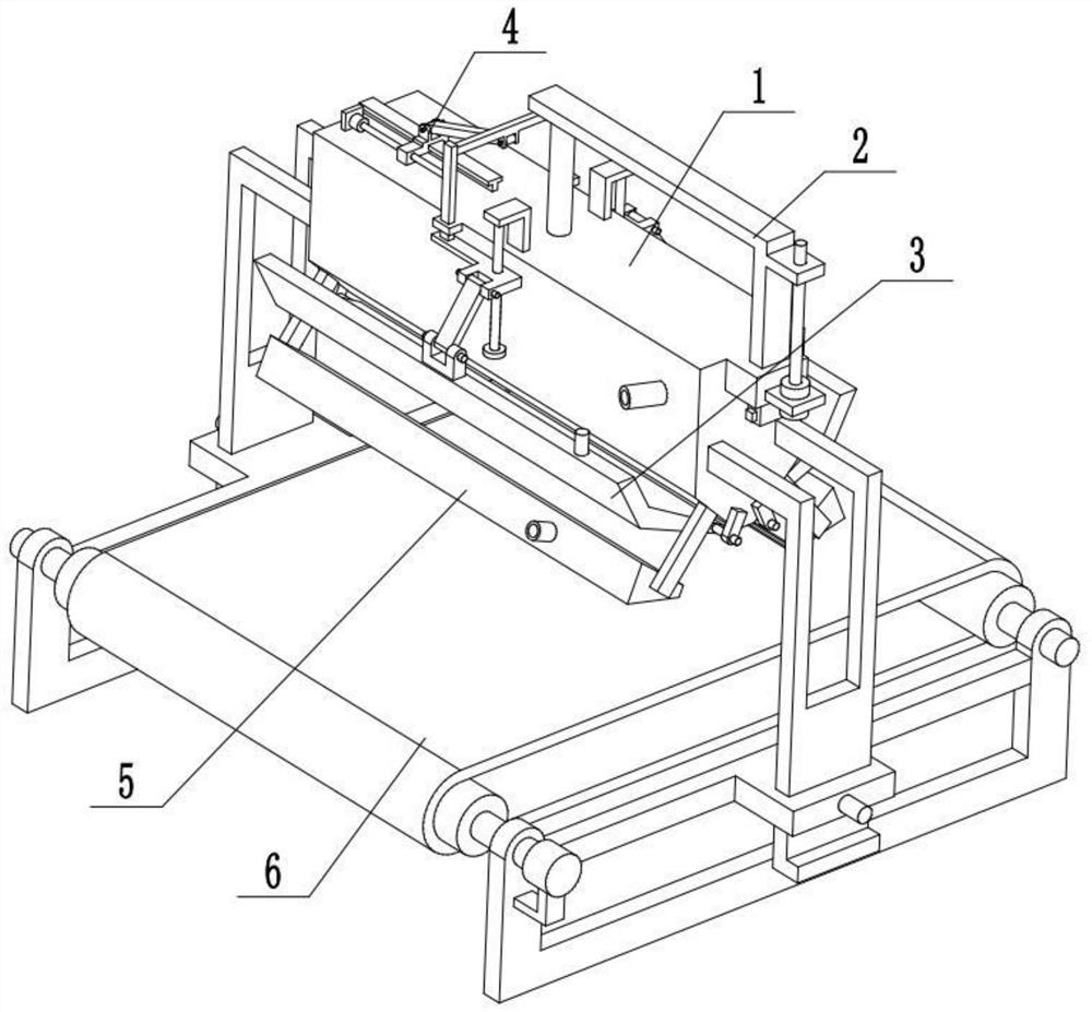
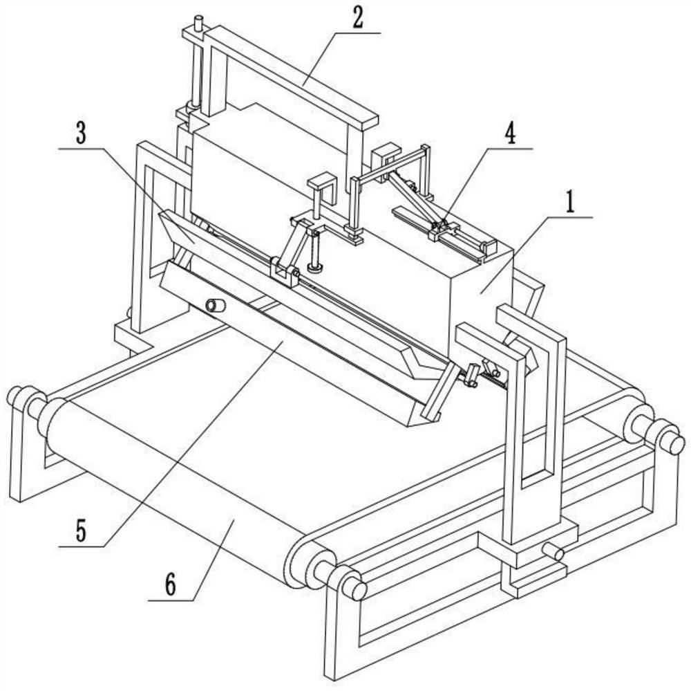
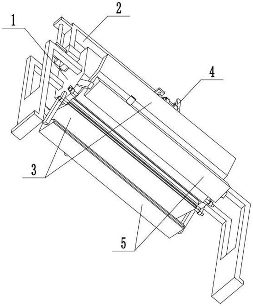
[0033] Combine below Figure 1-9 Describe this embodiment, a method for preparing a hydrophobic melt-blown cloth,
[0034] Include the following steps:
[0035] Raw solution addition: add the raw material solution, and the raw material solution is sprayed out;
[0036] Drawing: high temperature airflow draws the raw material solution to form ultrafine fibers;
[0037] Cooling: the extruded ultrafine fibers are bonded under the action of self-bonding, and the cooling airflow makes the extruded ultrafine fibers form a melt-blown cloth;
[0038] Transportation: the melt blown cloth is transported to the next station;
[0039] Angle adjustment: adjust the angle of high-temperature airflow to obtain melt-blown cloth with good fiber shape;
[0040] The method for preparing hydrophobic melt-blown cloth also relates to a preparation device for hydrophobic melt-blown cloth;
[0041]The hydrophobic melt-blown cloth preparation device includes a melt-blown die head assembly 1, an ex...
specific Embodiment approach 2
[0043] Combine below Figure 1-9 To illustrate this embodiment, the meltblown die head assembly 1 includes a nozzle 1-1, a liquid inlet pipe 1-2 with a control valve, a side carriage 1-3, a sliding sleeve 1-4, a T-shaped bar 1- 5. The side fixing sleeve 1-6 and the injection port 1-7; the liquid inlet pipe 1-2 is fixedly connected and communicated with the nozzle 1-1, and the two ends of the nozzle 1-1 are respectively fixedly connected with a side carriage 1-3, The two side sliding frames 1-3 are all connected with the receiving device 6, the sliding sleeve 1-4 and the T-shaped bar 1-5 are fixedly connected to the front and rear ends of the liquid inlet pipe 1-2 respectively, and the two side fixing sleeves 1- 6 are symmetrically and fixedly connected to the left and right ends of the nozzle 1-1, the extruding device 2 is connected with the nozzle 1-1, and the high-temperature air flow generator assembly 3 is symmetrically arranged at the lower end of the nozzle 1-1. When in...
specific Embodiment approach 3
[0045] Combine below Figure 1-9 To illustrate this embodiment, the extrusion discharge device 2 includes a first motor 2-1, a screw 2-2, an L-shaped frame 2-3, a telescopic rod 2-4 and an extrusion plate 2-5; the first motor 2-1 is fixed on the nozzle 1-1 through the motor frame, the output shaft of the first motor 2-1 is connected to the screw rod 2-2 through a coupling, and the front end of the L-shaped frame 2-3 is connected to the screw rod 2-2 through thread fit. Above, the two ends of the telescopic rod 2-4 are respectively fixedly connected to the L-shaped frame 2-3 and the extruding plate 2-5, and the telescopic rod 2-4 is sealed and slidably connected to the upper end of the nozzle 1-1, and the extruding plate 2-5 The sliding fit is connected inside the nozzle 1-1, and the liquid inlet pipe 1-2 is located at the lower end of the extruding plate 2-5. The first motor 2-1 starts to drive the extrusion plate 2-5 to move downward through the screw rod 2-2, L-shaped frame...
PUM
 Abstract
Description
Claims
Application Information
 - R&D
- Intellectual Property
- Life Sciences
- Materials
- Tech Scout
- Unparalleled Data Quality
- Higher Quality Content
- 60% Fewer Hallucinations
Browse by: Latest US Patents, China's latest patents, Technical Efficacy Thesaurus, Application Domain, Technology Topic, Popular Technical Reports.
© 2025 PatSnap. All rights reserved.Legal|Privacy policy|Modern Slavery Act Transparency Statement|Sitemap|About US| Contact US: help@patsnap.com


