
Manufacturing method for transmission shaft

A manufacturing method and transmission shaft technology, applied in the field of transmission shaft manufacturing, can solve the problems of low material utilization rate, low surface quality, low production efficiency, etc., and achieve the effect of improving oxidation resistance

Inactive Publication Date: 2020-09-15
CHONGQING UNIV OF ARTS & SCI
View PDF0 Cites 2 Cited by
  • Summary
  • Abstract
  • Description
  • Claims
  • Application Information

AI Technical Summary

Problems solved by technology

[0007] The present invention intends to provide a manufacturing method of a transmission shaft to solve the problems of low material utilization rate, low production efficiency, low dimensional accuracy, low surface quality and high production cost in the existing transmission shaft processing method

Method used


Image

  • Manufacturing method for transmission shaft
  • Manufacturing method for transmission shaft
  • Manufacturing method for transmission shaft

Examples


Embodiment Construction

[0031] The present invention will be described in further detail below by means of specific embodiments:

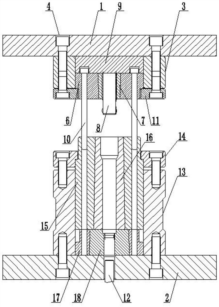
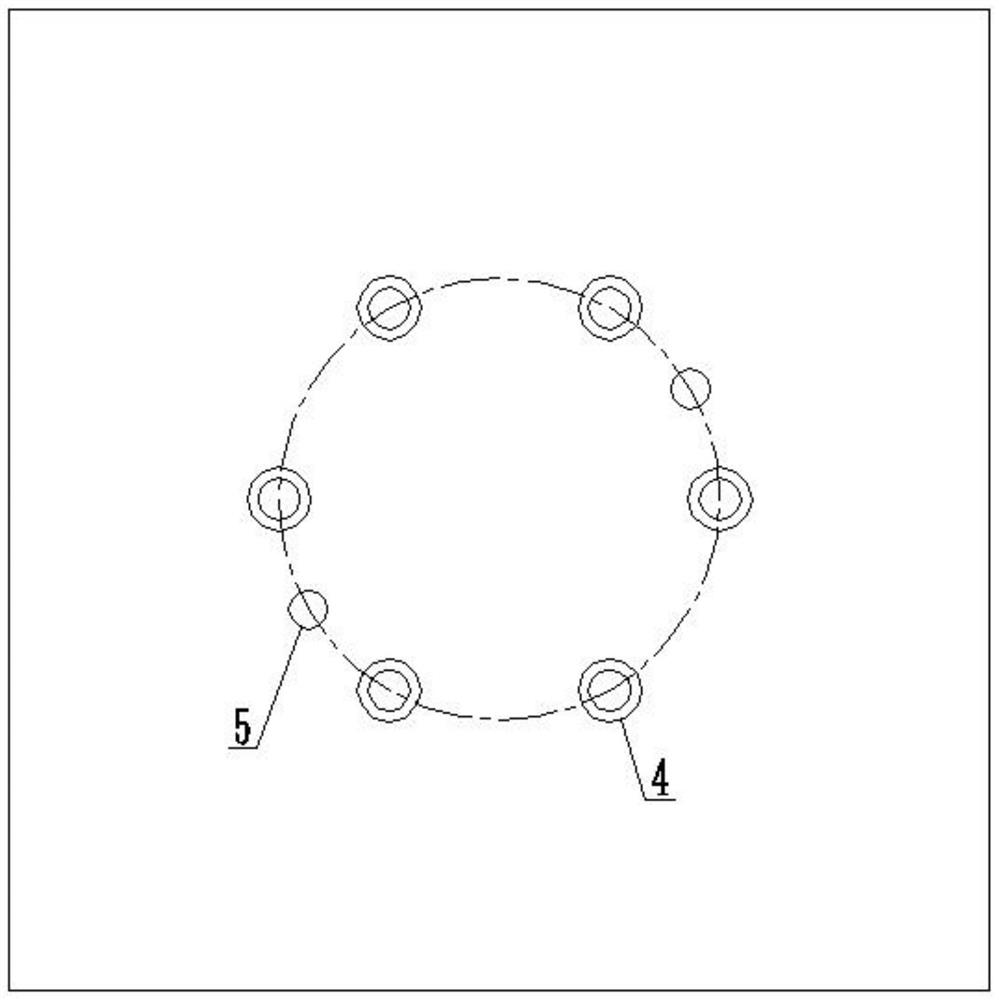
[0032] The reference signs in the accompanying drawings of the description include: upper die plate 1, lower die plate 2, upper die sleeve 3, threaded through hole 4, pin hole 5, upper die coat 6, upper die core 7, inner spline punch 8, upper die Die backing plate 9, guide post 10, upper mold pressing plate 11, ejector rod 12, lower mold base 13, lower mold pressing plate 14, lower mold outer cover 15, lower die core 16, spline outer cover 17, spline die core 18.

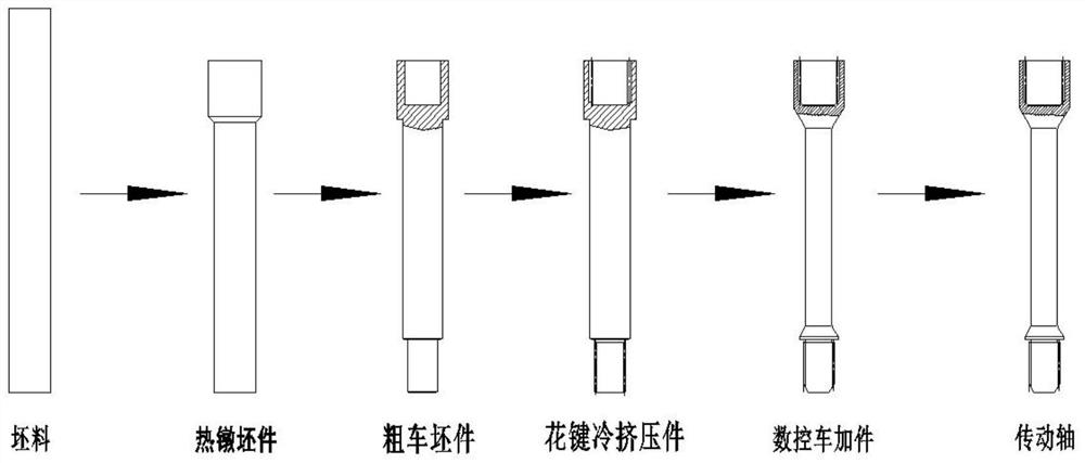
[0033] The embodiment is basically as attached figure 1 And attached figure 2 Shown: a manufacturing method of a transmission shaft, comprising:

[0034]S102: Saw and blank the round steel on a band sawing machine to obtain a billet, then perform local high-frequency induction heating on the upper end of the billet, and then place the heating on the upper end of the billet in the hot upsetting mold on the hy...


PUM


Abstract

The invention discloses a manufacturing method for a transmission shaft, and particularly relates to the technical field of machine manufacturing. The manufacturing method for the transmission shaft comprises the steps that round steel is subjected to local hot upsetting treatment to obtain a hot upsetting blank; the hot upsetting blank is drilled and turned to form an inner hole, and turning is carried out on the hot upsetting blank to reduce the diameter of the hot upsetting blank to obtain a rough turning blank; the rough turning blank is subjected to tooth extrusion forming machining treatment through using a cold extrusion tooth extrusion forming method to obtain a spline cold extrusion part with an inner spline and an outer spline; and the spline cold extrusion part is turned througha numerical control lathe to obtain a numerical control machined part, and finally, two outer circle surfaces on the numerical control machined part are ground to manufacture the transmission shaft.The technical scheme of the manufacturing method is adopted, the problem that an existing machining method for the transmission shaft is low in material utilization rate, low in production efficiency,low in dimensional precision, low in surface quality and high in production cost is solved, and the method can be used for manufacturing the transmission shaft with high precision.

Description

technical field [0001] The invention relates to the technical field of mechanical manufacturing, in particular to a manufacturing method of a transmission shaft. Background technique [0002] The transmission shaft is one of the key parts for power transmission in various mechanical equipment. It is a slender shaft coupling with involute tooth-shaped internal splines and external splines, a minimum diameter of φ18mm, and a total length of 225mm. It is used to transmit the power in the mechanical equipment from one mechanical mechanism to another in parallel, so that the other mechanical mechanism can generate some kind of mechanical movement after obtaining power. [0003] Present drive shafts are usually manufactured by metal cutting on lathes, gear shaping machines, hobbing machines or spline milling machines. In this conventional cutting process, the outer circle and inner circle of the transmission shaft are all cut on the lathe. For the slender shaft parts such as the ...

Claims


Application Information

Patent Timeline
IPC IPC(8): B23P15/14
CPCB23P15/14
Inventor 伍太宾
Owner CHONGQING UNIV OF ARTS & SCI
Learn More