Horizontal slicing equipment for Chinese yam processing and slicing method
A technology of horizontal slicing and yam, applied in metal processing and other directions, can solve the problems of accidental scratches, inconvenient use, time-consuming and labor-intensive thermal manual slicing, etc., to reduce the contact surface, improve the drying effect, and the cutting and cutting is simple and convenient. Effect
- Summary
- Abstract
- Description
- Claims
- Application Information
AI Technical Summary
Problems solved by technology
Method used
Image

Examples
Embodiment 1
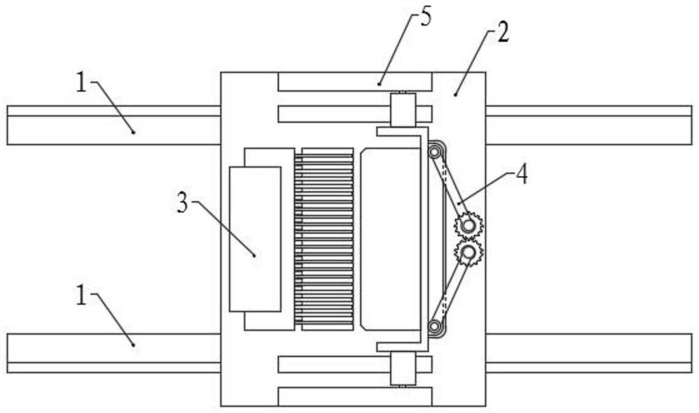
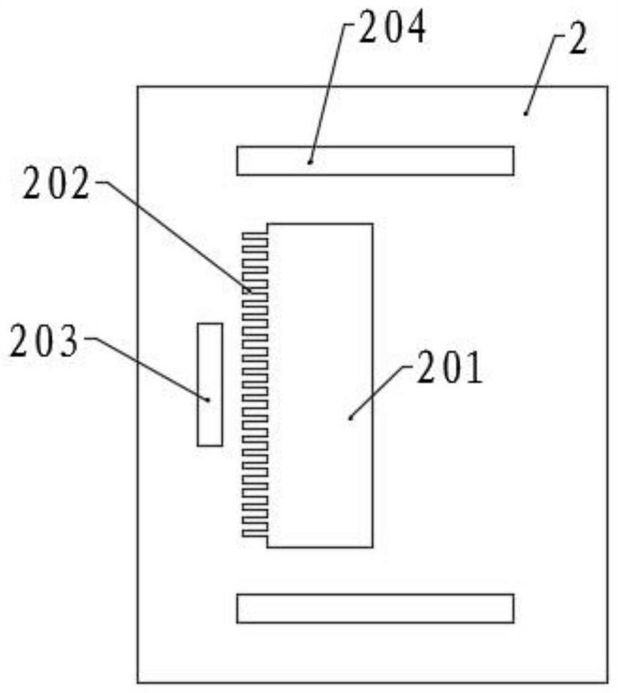
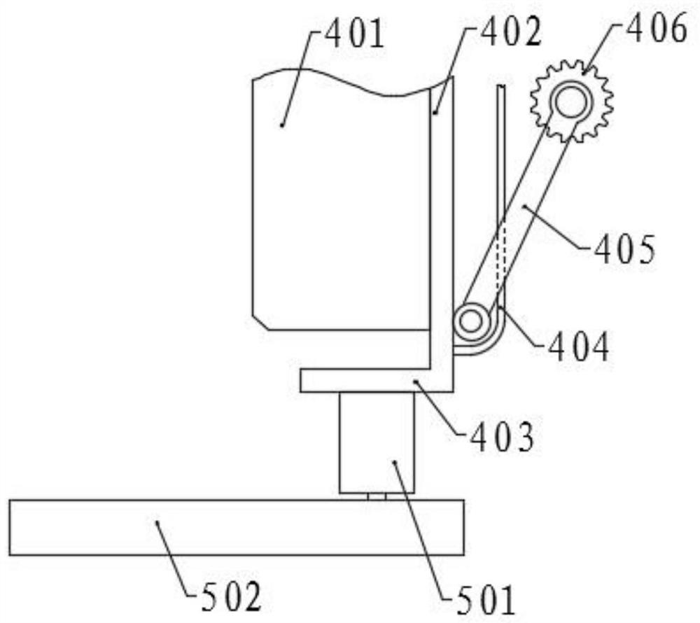
[0052] Please refer to the accompanying drawings, the present invention provides a technical solution: a horizontal slicing device for yam processing, including a workbench 2, the bottom surface of the workbench 2 is symmetrical and is fixed with two slide rails 1 in parallel, and the top of the workbench 2 The middle of the surface is provided with a chute 201, and the left side wall of the chute 201 is evenly provided with a plurality of vertical chutes 202 along the length direction. Be provided with unloading mechanism 3, the right side wall bottom of material storage box 6 is provided with blade groove 701, the outside of blade groove 701 is provided with slicing mechanism 4, and both sides of slicing mechanism 4 are symmetrically provided with moving mechanism 5, and moving mechanism 5 and The slicing mechanism 4 is correspondingly connected, and a placing plate 7 is slidably connected between the two slide rails 1 , and the placing plate 7 is correspondingly connected wi...
Embodiment 2
[0055] The structure of this embodiment is basically the same as that of Embodiment 1, except that, preferably, the unloading mechanism 3 includes an L-shaped fixed frame 301, and the vertical plate of the fixed frame 301 is fixedly connected with the workbench 2, and the vertical plate is fixed There is a motor, and the output shaft of the motor is fixed with a cam 305, and the position corresponding to the cam 305 on the workbench 2 is provided with a rotation groove 203, so as to prevent the wheel surface from contacting the workbench 2 when the cam 305 rotates, which hinders the rotation of the cam 305 , a movable plate 302 is provided between the cam 305 and the horizontal plate of the fixed frame 301, and a spring is arranged between the movable plate 302 and the horizontal plate, and the right end bottom of the movable plate 302 is evenly fixed with a plurality of vertical The first sliding piece 303, the first sliding piece 303 is slidably connected in the vertical chut...
Embodiment 3
[0067] The structure of this embodiment is basically the same as that of Embodiment 2, the difference is that a support bar 704 is slidably connected to the sheet groove 701, and a plurality of springs are evenly arranged between the support bar 704 and the bottom surface of the sheet groove 701, and the support bar 704 is evenly provided with a plurality of flow guide holes 705 along the length direction, and the top surface of the placement plate 7 is also uniformly provided with a plurality of flow guide holes 705, and the bottom ends of the flow guide holes 705 are inclined to the sheet groove 701, and are aligned with the sheet groove 701. The groove 701 is connected, and the support bar 704 is used to prevent the yam slices from accidentally being stuck in the slice groove 701 during the subsequent movement, and through the guide hole 705, the hot air flow during subsequent drying can fully contact the yam slice through the guide hole 705.
[0068]The left side of the bot...
PUM
 Abstract
Description
Claims
Application Information
 - R&D
- Intellectual Property
- Life Sciences
- Materials
- Tech Scout
- Unparalleled Data Quality
- Higher Quality Content
- 60% Fewer Hallucinations
Browse by: Latest US Patents, China's latest patents, Technical Efficacy Thesaurus, Application Domain, Technology Topic, Popular Technical Reports.
© 2025 PatSnap. All rights reserved.Legal|Privacy policy|Modern Slavery Act Transparency Statement|Sitemap|About US| Contact US: help@patsnap.com