Performance failure testing device and method for low-temperature valve for LNG
A technology for failure testing and valves, which is applied in mechanical valve testing and other directions, and can solve problems such as sealing and locking failures
- Summary
- Abstract
- Description
- Claims
- Application Information
AI Technical Summary
Problems solved by technology
Method used
Image

Examples
Embodiment Construction
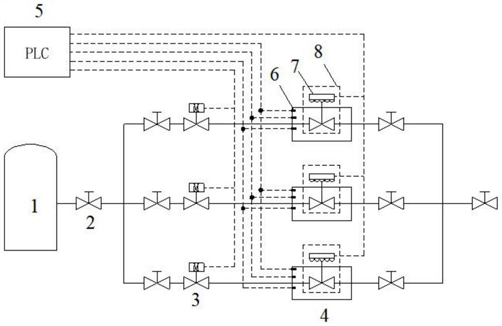
[0026] see figure 1 , 2 , a performance failure test device for cryogenic valves for LNG, including a medium gas source supply system, a closed box and a cryogenic valve test station.
[0027] The low-temperature valve testing station is located in a closed box. The low-temperature valve testing station is equipped with a driving mechanism and a low-temperature valve to be tested connected to it. The driving mechanism is composed of a torque and displacement sensor and a servo motor connected to it. No less than 3 sets of nitrogen concentration sensors and temperature sensors are installed on the top, middle and bottom of one side wall of the closed box, and an air outlet pipe is installed on the other side wall.
[0028] The medium gas source supply system includes a liquid nitrogen storage tank, a liquid nitrogen gas supply main pipe and a multi-way branch distribution pipe, wherein the inlet of the liquid nitrogen gas supply main pipe is connected to the liquid nitrogen st...
PUM
| Property | Measurement | Unit |
|---|---|---|
| Diameter | aaaaa | aaaaa |
| Diameter | aaaaa | aaaaa |
Abstract
Description
Claims
Application Information
 - Generate Ideas
- Intellectual Property
- Life Sciences
- Materials
- Tech Scout
- Unparalleled Data Quality
- Higher Quality Content
- 60% Fewer Hallucinations
Browse by: Latest US Patents, China's latest patents, Technical Efficacy Thesaurus, Application Domain, Technology Topic, Popular Technical Reports.
© 2025 PatSnap. All rights reserved.Legal|Privacy policy|Modern Slavery Act Transparency Statement|Sitemap|About US| Contact US: help@patsnap.com