Fuel cell stack and method of producing dummy cell

一种燃料电池堆、制造方法的技术,应用在燃料电池、燃料电池的形状/形式、最终产品制造等方向,能够解决扩散性下降、端部侧低温、燃料电池堆发电稳定性下降等问题,达到提高发电稳定性的效果

Active Publication Date: 2020-09-15
HONDA MOTOR CO LTD
View PDF5 Cites 1 Cited by
  • Summary
  • Abstract
  • Description
  • Claims
  • Application Information

AI Technical Summary

Problems solved by technology

[0004] However, the end side of the laminated body in the stacking direction (hereinafter also simply referred to as the end side) is easier to dissipate on the end side than the central side in the stacking direction of the laminated body because heat radiation through the terminal block or the like is promoted. become cryogenic
When the end side of the stack becomes cold and dew condensation occurs due to the influence of external air temperature, etc., the diffusivity of fuel gas and oxidant gas (reactive gas) may decrease, and the power generation stability of the fuel cell stack may decrease.

Method used


Image

  • Fuel cell stack and method of producing dummy cell
  • Fuel cell stack and method of producing dummy cell
  • Fuel cell stack and method of producing dummy cell

Examples


Embodiment Construction

[0034] Preferred embodiments will be listed, and a fuel cell stack and a method of manufacturing a dummy cell according to the present invention will be described in detail with reference to the drawings. In addition, in the following figures, components that are the same or that exhibit the same functions and effects may be given the same reference numerals and redundant descriptions may be omitted.

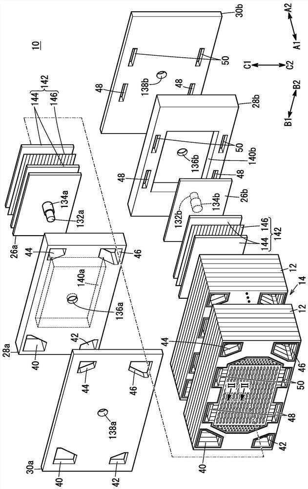
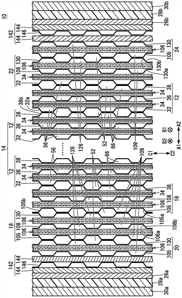
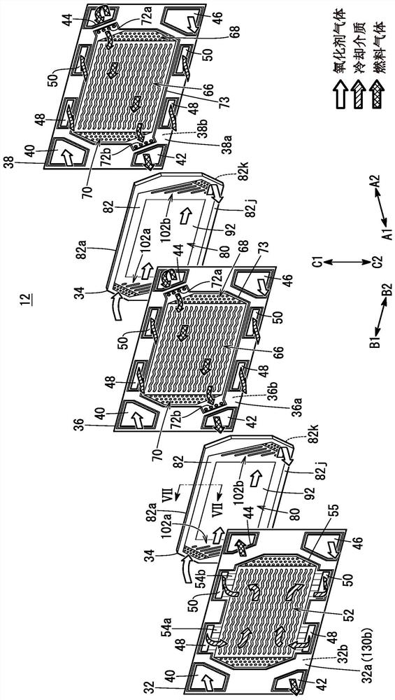
[0035] Such as figure 1 with figure 2 As shown, the fuel cell stack 10 according to this embodiment includes a stacked body 14 in which a plurality of power generating cells 12 are stacked in the horizontal direction (arrow A1, A2 direction) or in the gravity direction (arrow C1, C2 direction). The fuel cell stack 10 is mounted, for example, on a fuel cell vehicle such as a fuel cell electric vehicle (not shown).

[0036] Such as figure 2As shown, on one end side (arrow A1 side) of the stacked body 14 in the stacking direction, the first end power generation unit 16 , the f...


PUM


Abstract

Fuel cell stack and method of producing dummy cell. A fuel cell stack at least includes a stack body including a plurality of power generation cells each having a membrane electrode assembly stacked in a stacking direction, and a first dummy cell provided at one end of the stack body in the stacking direction. A dummy structural body of the first dummy cell is joined to a dummy resin frame memberthrough an adhesive layer which adheres a first outer peripheral portion and a second outer peripheral portion, and inner periphery of the dummy resin frame member to each other.

Description

technical field [0001] The present invention relates to a fuel cell stack including a stack in which a plurality of power generating cells are stacked, and a dummy cell arranged at at least one end in the stacking direction of the stack, and a method for manufacturing the dummy cell. It has an electrolyte membrane-electrode structure and a resin frame member surrounding the outer periphery of the electrolyte membrane-electrode structure. Background technique [0002] In general, a solid polymer fuel cell employs a solid polymer electrolyte membrane (hereinafter also simply referred to as an electrolyte membrane) formed of a polymer ion exchange membrane. A fuel cell includes an electrolyte membrane-electrode structure (MEA) in which an anode electrode is arranged on one surface of an electrolyte membrane and a cathode electrode is arranged on the other surface. [0003] The electrolyte membrane-electrode structure is sandwiched between separators to form a power generating ...

Claims


Application Information

Patent Timeline
Patent Type & Authority Applications(China)
IPC IPC(8): H01M8/2465H01M8/04701H01M8/2404H01M8/00F16L59/02
CPCH01M8/2465H01M8/2404H01M8/006H01M8/04701F16L59/029F16L59/02H01M8/0239H01M8/0267H01M8/0271H01M8/04029H01M2008/1095H01M8/242Y02E60/50Y02P70/50H01M8/1004
Inventor 井上大辅
Owner HONDA MOTOR CO LTD
Why Eureka
Try Eureka