Power electronic transformer system fault reconstruction method

A technology for power electronics and system failures, applied in the direction of adjusting electrical variables, control/regulation systems, instruments, etc., to achieve the effects of enhancing reliability, improving stability, and reducing switching frequency

Active Publication Date: 2020-09-15
SOUTHWEST JIAOTONG UNIV
View PDF11 Cites 2 Cited by
  • Summary
  • Abstract
  • Description
  • Claims
  • Application Information

AI Technical Summary

Problems solved by technology

[0004] The purpose of the present invention is to provide a power electronic transformer system fault reconfiguration method, which can effectively solve the problem of switching state S in the existing reconfiguration technology. i The technical problems of the "stepping" transition

Method used


Image

  • Power electronic transformer system fault reconstruction method
  • Power electronic transformer system fault reconstruction method
  • Power electronic transformer system fault reconstruction method

Examples


Embodiment Construction

[0024] The present invention will be described in detail below in conjunction with the accompanying drawings and specific embodiments.

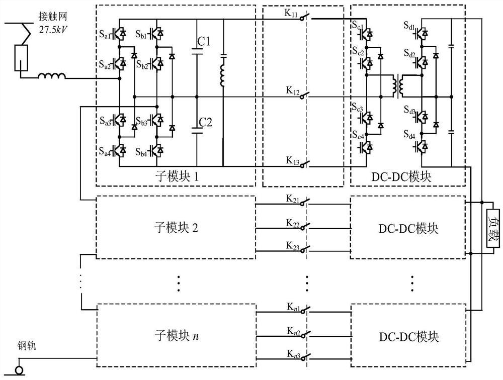
[0025] According to the characteristics of the power electronic transformer, the single-phase diode-clamped three-level cascaded rectifier of its front-end equipment has a certain degree of redundancy. It can realize the forced charging and discharging of the DC side capacitors C1 and C2 through a specific switching sequence, thereby regulating The DC side voltage realizes the fault reconstruction of the DC link; therefore, the present invention makes full use of this characteristic, and proposes a reconstruction method suitable for DC link faults of power electronic transformers in traditional high-speed train systems. When the DC link fails, the DC side capacitor is used to reconfigure the system, and the system can still operate safely and reliably while ensuring the output power quality.

[0026] Such as figure 1 Shown is the topological...


PUM


Abstract

The invention discloses a power electronic transformer system fault reconstruction method, and belongs to the technical field of power electronics. The middle protection switch is formed by connectingthree switch groups which are opened and closed at the same time with an upper output port, a clamping midpoint and a lower output port of the cascade rectifier in series respectively; when a power electronic transformer operates normally, the intermediate protection switch is in a closed state, and a DC-DC converter is in a put-in state; when the direct-current link of the power electronic transformer fails, the intermediate protection switch is quickly switched off; the method specifically comprises the following steps: carrying out carrier stacking calculation to generate a level k, and judging an area R where a modulation wave u* is located; according to k and R, establishing a switching state equation of an n sub-module cascade rectifier, and establishing a first switching state table; and acquiring and sorting the DC output voltage of each sub-module, performing smooth optimization processing on the obtained switching state, establishing a second switching state table, and matching the switching state in the second switching state table to each sub-module so that the reconstruction of the DC link fault is completed.

Description

technical field [0001] The invention belongs to the technical field of power electronics. Background technique [0002] In recent years, with the development of multi-level power electronics technology, the demand for power electronic transformers suitable for traction drive systems of high-speed trains has been increasing; the transformers are mainly composed of single-phase cascaded converters, intermediate isolating composition. Since the single-phase three-level mid-point clamped cascaded rectifier in the front stage has the characteristics of "series voltage division", when the DC link at the back end fails and the power of each sub-module is unbalanced, if it is not controlled, it may Due to the voltage drift of individual sub-modules, other components in the circuit are damaged; in extreme cases, when a certain DC link is cut off due to a fault, the output voltage of the cascaded rectifier will increase due to the "open circuit" of the faulty sub-module , causing th...

Claims


Application Information

Patent Timeline
Patent Type & Authority Applications(China)
IPC IPC(8): H02M1/00H02M1/32H02H7/125H02M7/5387H02M3/335
CPCH02M1/00H02M1/32H02H7/125H02M7/53873H02M3/33576H02M1/322H02M1/325H02M1/007Y02E60/60
Inventor 何晓琼余昊伦高仕斌
Owner SOUTHWEST JIAOTONG UNIV
Why Eureka
Try Eureka