Orthopedic operation drill
An orthopaedic surgery and drill technology, which can be used in surgery, bone drill guidance, medical science, etc., and can solve problems such as difficult positioning.
- Summary
- Abstract
- Description
- Claims
- Application Information
AI Technical Summary
Problems solved by technology
Method used
Image

Examples
Embodiment 1
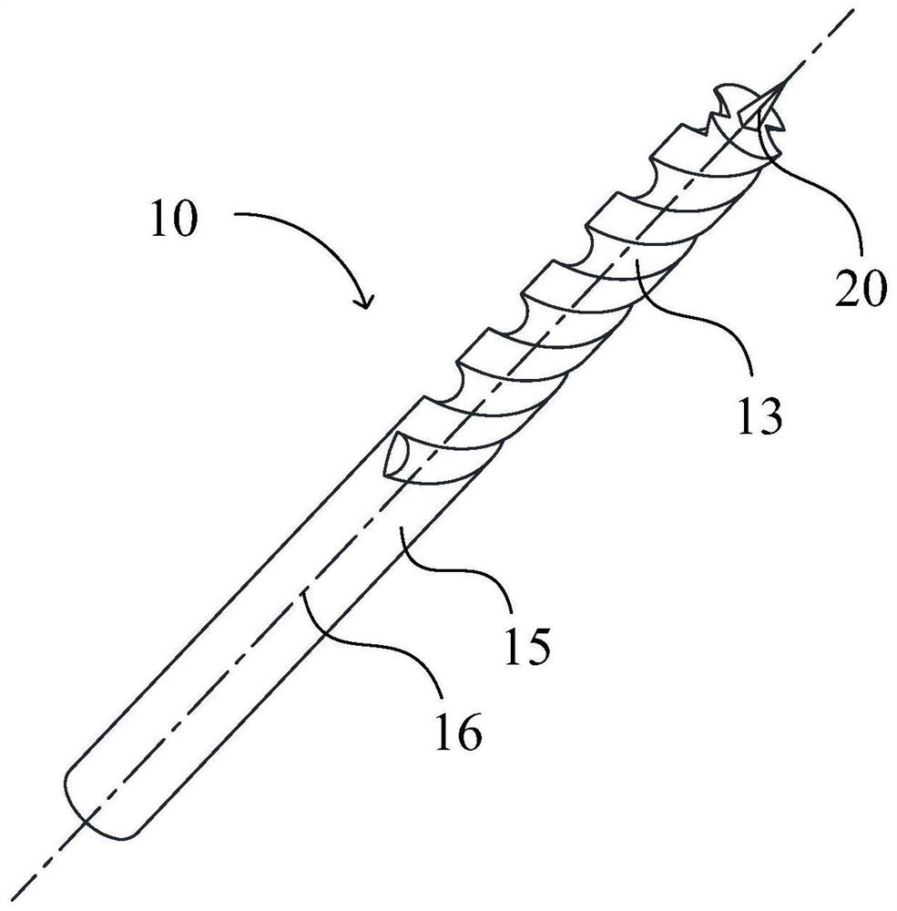
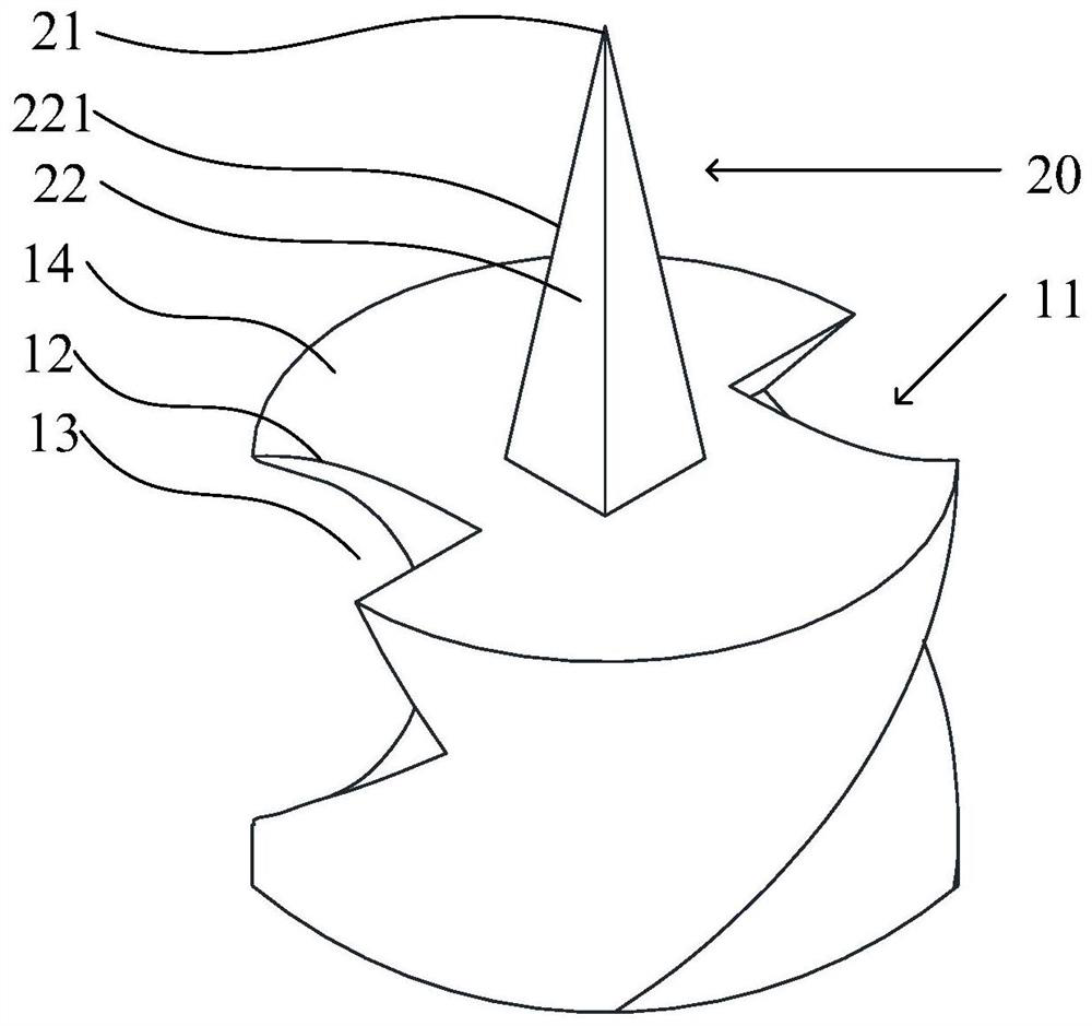
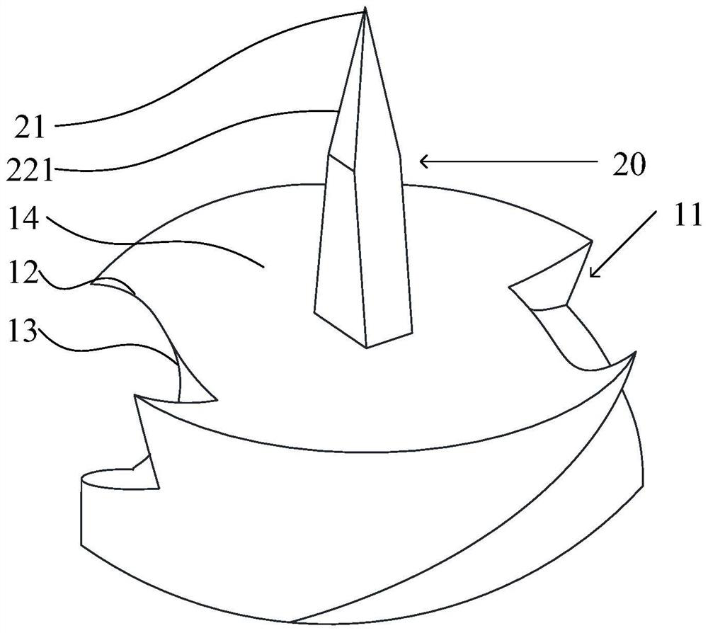
[0119] Such as Figure 1-Figure 6 As shown, the present embodiment is a drill 10 for orthopedic surgery. The drill 10 for orthopedic surgery includes a drill body 11 and a positioning piece 20. One end of the positioning piece 20 is connected to the end face 14 of the drill body 11. The other end of the positioning piece 20 is One end has a tip 21 for determining where the orthopedic surgical drill 10 drills into cartilage or bone. In this embodiment, the tip 21 of the positioning member 20 is used to simply and conveniently insert the orthopedic surgery drill 10 into the cartilage or bone, which is beneficial to avoid the sliding of the orthopedic surgery drill 10 on the cartilage or bone, thereby making the orthopedic surgery drill 10 Able to accurately drill holes at pre-designed implant locations. The orthopedic surgery drill 10 of this embodiment is beneficial to simple and convenient drilling of cartilage or bone, improving drilling efficiency, and improving the accurac...
Embodiment 2
[0131] Such as Figure 7-Figure 9 As shown, this embodiment is a drill 10 for orthopedic surgery, and this embodiment is basically the same as Embodiment 1, except that the limiting member 30 of this embodiment is the first limiting member 310 . The outer peripheral surface of the drill body 11 is provided with a spiral groove 13, the first limiting member 310 is sleeved on the outside of the drill body 11, and the inner surface of the first limiting member 310 is provided with a raised portion 301, and the raised portion 301 is embedded in the spiral groove 13. In this embodiment, the first stopper 310 sleeved on the outside of the drill body 11 is used, so that the orthopedic surgery drill 10 cannot continue to drill into cartilage or bone. By adjusting the distance between the first limiting member 310 and the end surface 14 of the drill body 11 , the adjustment of the drilling depth is realized, which is beneficial to improving the accuracy of the position and depth of th...
Embodiment 3
[0142] Such as Figure 10-Figure 14 As shown, this embodiment is a drill 10 for orthopedic surgery. This embodiment is basically the same as Embodiment 1, except that the limiting member 30 of this embodiment is the second limiting member 320, and the drill body 11 Also make changes accordingly. The second limiter 320 is sleeved on the outside of the drill body 11, and the outer surface of the drill body 11 is provided with a plurality of draw-in grooves 17, and the draw-in grooves 17 are arranged along the axis 16 of the drill body 11. The second limiter 320 is provided with The latching slot 17 corresponds to the latching teeth 31 , and the latching teeth 31 are used to detachably latch the latching slot 17 . In this embodiment, the second limiting member 320 sleeved on the outside of the drill body 11 is used, so that the orthopedic surgery drill 10 cannot continue to drill into cartilage or bone. By adjusting the distance between the second limiting member 320 and the en...
PUM
 Abstract
Description
Claims
Application Information
 - R&D
- Intellectual Property
- Life Sciences
- Materials
- Tech Scout
- Unparalleled Data Quality
- Higher Quality Content
- 60% Fewer Hallucinations
Browse by: Latest US Patents, China's latest patents, Technical Efficacy Thesaurus, Application Domain, Technology Topic, Popular Technical Reports.
© 2025 PatSnap. All rights reserved.Legal|Privacy policy|Modern Slavery Act Transparency Statement|Sitemap|About US| Contact US: help@patsnap.com