Solar-driven carbon dioxide trapping tower and operation method thereof

A technology of carbon dioxide and solar energy, applied in solar thermal power generation, chemical instruments and methods, separation methods, etc., can solve the problems of poor separation effect, difficult absorption, and low adsorption amount, and achieve the goal of improving efficiency, increasing content, and efficient absorption Effect

Pending Publication Date: 2020-09-18
XI AN JIAOTONG UNIV
View PDF0 Cites 0 Cited by
  • Summary
  • Abstract
  • Description
  • Claims
  • Application Information

AI Technical Summary

Problems solved by technology

[0003] There are three main methods of carbon dioxide capture today: 1. Absorption method; 2. Adsorption method; 3. Membrane separation method; Among them, the absorption method uses the properties of carbon dioxide acid gas to chemically react with weakly alkaline substances, and then decomposes into carbon dioxide gas , but this method is difficult to apply to low concentrations of CO 2 Absorption, a stronger driving force is required to drive the capture liquid for CO 2 Absorption; adsorption method is to use some solid adsorbents to CO 2 Adsorption is carried out, but this method has a small amount of adsorption and poor selectivity, and CO is mainly carried out by temperature difference or pressure difference. 2 The membrane separation method is to use polymeric polymer materials, such as polyimide, cellulose acetate and other materials to make thin films, use the different permeability of the thin film to different gases to separate, and drive the gas through the pressure difference on both sides of the thin film separation, but the separation effect of this method is very poor, and for low concentrations of CO in the atmosphere 2 (350-450ppm (ml / m 3 )) Difficult to efficiently absorb
[0004] In summary, the current existing devices and methods are unable to efficiently absorb low-concentration carbon dioxide in the atmosphere, and there is an urgent need for a new solar-driven carbon dioxide capture tower and its operating method

Method used


Image

  • Solar-driven carbon dioxide trapping tower and operation method thereof

Examples


Embodiment Construction

[0035] In order to make the purpose, technical effects and technical solutions of the embodiments of the present invention more clear, the technical solutions in the embodiments of the present invention are clearly and completely described below in conjunction with the accompanying drawings in the embodiments of the present invention; obviously, the described embodiments It is a part of the embodiment of the present invention. Based on the disclosed embodiments of the present invention, other embodiments obtained by persons of ordinary skill in the art without making creative efforts shall all fall within the protection scope of the present invention.

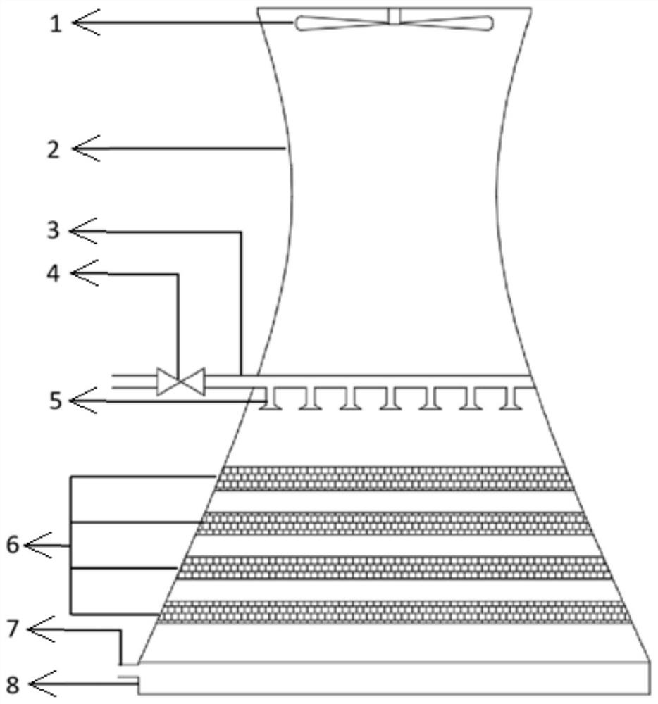
[0036] see figure 1 , a solar-driven carbon dioxide capture tower according to an embodiment of the present invention, comprising: a rich liquid pool 8, a rich liquid outlet 7, a trap packing 6, a pressurized nozzle 5, a throttle valve 4, a lean liquid delivery pipeline 3, a double Curved collection tower 2 and ventilation dev...


PUM


Abstract

The invention discloses a solar-driven carbon dioxide trapping tower and an operation method thereof. The carbon dioxide trapping tower comprises a hyperbolic trapping tower, a solar absorbing coatingis arranged on the outer wall of the hyperbolic trapping tower and is used for absorbing gas in a solar heating tower; an air extractor is arranged at the top of the hyperbolic trapping tower, a pregnant solution outlet is formed in the bottom of the hyperbolic trapping tower; a barren liquor pool and a trapping filler are sequentially arranged between the air extractor and the pregnant solutionoutlet from top to bottom; the barren liquor pool is provided with a plurality of outlets, pressurizing nozzles are arranged at the outlets; and a barren liquor conveying pipeline is arranged at the inlet of the barren liquor pool and used for being communicated with the outside. By enhancing the mass transfer rate between the carbon dioxide capture liquid and the atmosphere, the carbon dioxide trapping efficiency is enhanced, and low-concentration carbon dioxide in the atmosphere can be efficiently absorbed.

Description

technical field [0001] The invention belongs to the technical field of carbon dioxide capture, and in particular relates to a solar-driven carbon dioxide capture tower and an operation method thereof. Background technique [0002] With the continuous improvement of global industrialization in recent years, carbon dioxide emissions have also continued to increase. In 2019, global carbon dioxide emissions have reached 36.8 billion tons. Reducing carbon emissions has become a common problem that all mankind needs to face. Existing carbon dioxide capture technologies are mainly used to capture and process high-concentration carbon dioxide; but in fact, what needs to be dealt with is low-concentration carbon dioxide in the atmosphere. [0003] There are three main methods of carbon dioxide capture today: 1. Absorption method; 2. Adsorption method; 3. Membrane separation method; Among them, the absorption method uses the properties of carbon dioxide acid gas to chemically react wi...

Claims


Application Information

Patent Timeline
Patent Type & Authority Applications(China)
IPC IPC(8): B01D53/18F24S70/20
CPCB01D53/18F24S70/20Y02E10/40
Inventor 李娜黄少轩朱建军徐德全王梓程周屈兰
Owner XI AN JIAOTONG UNIV
Why Eureka
Try Eureka