
Water-cooling type compressor for shale gas recycling

A shale gas and compressor technology, applied in mechanical equipment, machines/engines, liquid variable volume machinery, etc., can solve the problems of affecting the atmospheric environment, explosion, easy explosion, etc., to improve recycling efficiency, reduce Risk of explosion, effect of preventing excessive temperature

Inactive Publication Date: 2020-09-18
德耐尔能源装备有限公司
View PDF8 Cites 0 Cited by
  • Summary
  • Abstract
  • Description
  • Claims
  • Application Information

AI Technical Summary

Problems solved by technology

[0006] However, the current compression and separation equipment still has the following disadvantages: 1. Lack of equipment that can simultaneously or continuously compress and separate, resulting in low shale gas recycling efficiency and high cost; 2. During the long-term compression work of the compression device, Heating phenomenon often occurs. Because natural gas is a flammable gas, if it is not cooled in time, it will cause the danger of explosion; 3. The compressed shale gas cannot be cooled by water, and the temperature of the compressed shale gas It is relatively high and prone to explosion. Therefore, we propose a water-cooled shale gas recovery compressor; 4. Poor filtering effect during oil-gas separation leads to the discharge of partially vaporized oil and affects the atmospheric environment; The pressure is detected and the pressure in the cylinder is too high, which is easy to explode the cylinder

Method used


Image

  • Water-cooling type compressor for shale gas recycling
  • Water-cooling type compressor for shale gas recycling
  • Water-cooling type compressor for shale gas recycling

Examples


Embodiment Construction

[0035] In order to make the objectives, technical solutions and advantages of the present invention clearer, the present invention will be further described in detail below in conjunction with the accompanying drawings. Obviously, the described embodiments are only a part of the embodiments of the present invention, rather than all of them. Based on the embodiments of the present invention, all other embodiments obtained by those of ordinary skill in the art without creative work shall fall within the protection scope of the present invention.

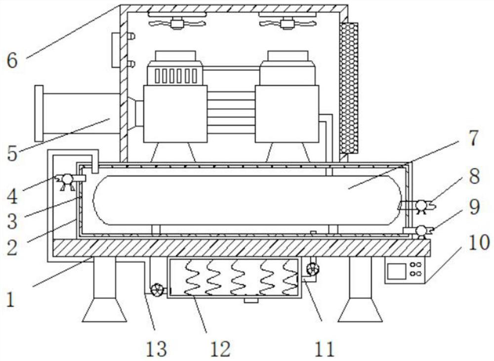
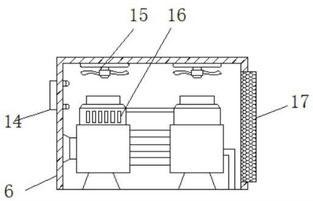
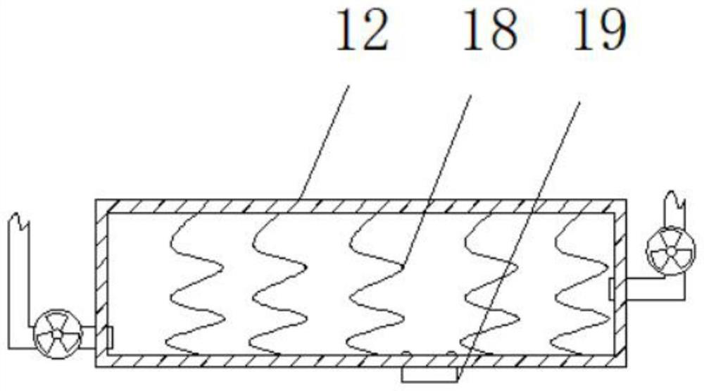
[0036] A water-cooled shale gas recovery compressor includes a compression device and an oil-gas separation device; the compression device includes a support base 1, a water-cooled box 2 is fixedly connected to the upper surface of the support base 1, and the water-cooled box 2 is filled inside There is a thermal insulation cotton 3, the left side wall of the water-cooled box 2 is inlaid and connected with a water inlet pipe 4, the upper s...


PUM


Abstract

The invention discloses a water-cooling type compressor for shale gas recycling. The water-cooling type compressor for shale gas recycling comprises a compression device and an oil-gas separation device. The compression device comprises a support base. A water cooling box is fixedly connected to the upper surface of the support base. The water cooling box is internally filled with thermal insulation cotton. A gas storage tank is mounted inside the water cooling box. A gas outlet pipe is connected to the right side wall of the gas storage tank in an inlaid manner. The oil-gas separation devicecomprises a cylinder body. A piston cylinder is in clearance connection to the inner side wall of the cylinder body. A crankshaft is mounted at the right side of the outer side wall of a piston rod and penetrates the right side of the outer side wall of the cylinder body. The other end of the crankshaft is provided with a crankshaft connecting rod. The other end of the crankshaft connecting rod isprovided with a second motor. A gas inlet valve is mounted at the left side of the outer side wall of the cylinder body. The gas outlet pipe communicates with the gas inlet valve. By means of the water-cooling type compressor for shale gas recycling, synchronous or continuous compression and separation can be achieved; the shale gas recycling efficiency can be greatly improved; the cost is lowered; safety and reliability are achieved; and the water-cooling type compressor can operate for a long time.

Description

Technical field [0001] The invention relates to the technical field of mechanical devices, in particular to a water-cooled compressor for shale gas recovery. Background technique [0002] Shale gas is deep and has the characteristics of self-generation and self-storage. Shale is both a source rock and a storage rock. Shale gas is a kind of natural gas, but the two concepts are not on the same level. Shale gas refers to the accumulation of natural gas mainly located in dark mud shale or high-carbon mud shale, with adsorption or free state as the main way of existence. In a sense, the formation of shale gas reservoirs is the result of large-scale retention of natural gas in the source rock. The mining of shale gas is relatively difficult. When it is extracted after separation or when recovering some poor-quality shale gas, its components (oil, gas, dark mud shale or high-carbon mud) are required. Shale and other magazines) currently lack effective compression and separation equi...

Claims


Application Information

Patent Timeline
Patent Type & Authority Applications(China)
IPC IPC(8): F04B35/04F04B39/06F04B39/10F04B39/16F04B41/02F04B51/00
CPCF04B35/04F04B39/06F04B39/066F04B39/16F04B51/00F04B39/1046F04B41/02
Inventor 余浪波赵迎普盛昌国
Owner 德耐尔能源装备有限公司
Learn More