An implantable molten ceramic material outflow device
A ceramic material, implanted technology, used in casting molding equipment, furnaces, lighting and heating equipment, etc., can solve the problems of rough surface, poor thermochemical stability, small thermal expansion and so on
- Summary
- Abstract
- Description
- Claims
- Application Information
AI Technical Summary
Problems solved by technology
Method used
Image
Examples
Embodiment 1
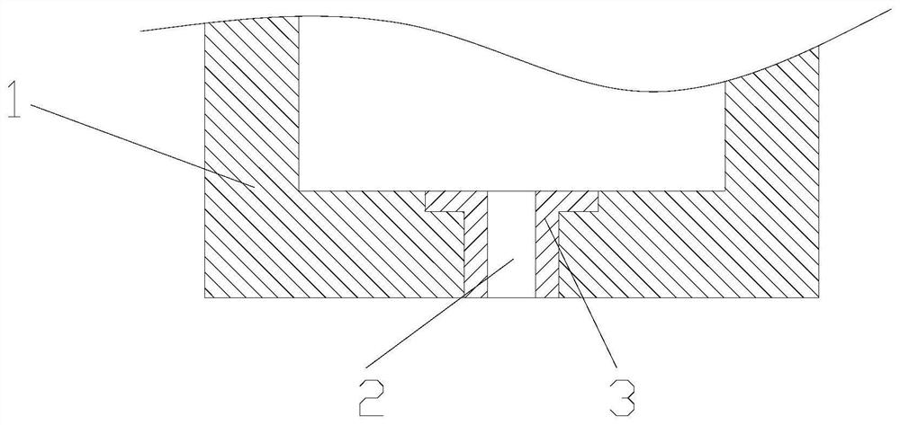
[0027] according to figure 1 As shown, an implantable molten ceramic material outflow device includes an outflow pipe 3, and the outflow pipe 3 is installed at the bottom of the furnace 1; the device can control the flow rate of the molten ceramic material through the outflow port 2, and realizes melting The stable flow control of ceramic materials not only ensures the particle size concentration of ceramic sand, but also ensures the quality of ceramic sand.
Embodiment 2
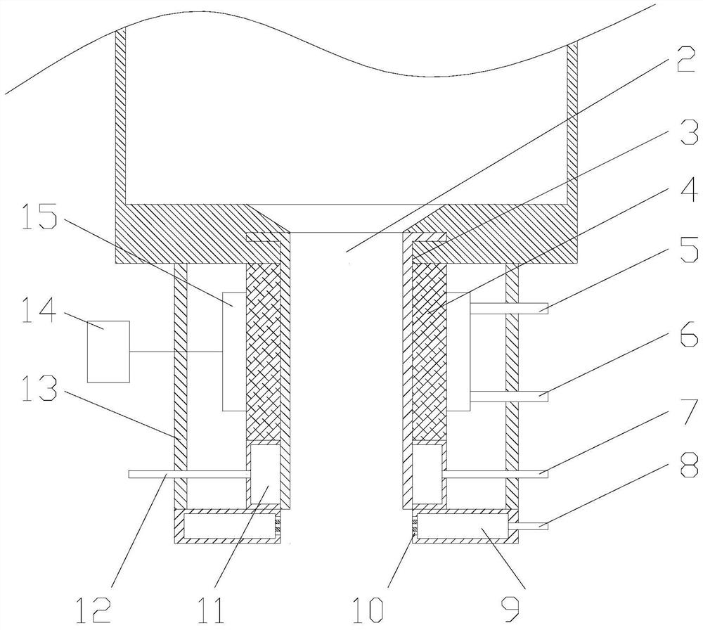
[0029] according to figure 2The difference from Example 1 is that the lower end of the outflow pipe 3 extends to the outside of the furnace 1, and an insulating refractory lining 4 and a protective shell 13 are installed on the outflow pipe 3 extending outside the furnace 1, so The heat-insulating and refractory lining 4 is set on the outside of the outlet pipe 3, and a first cooling jacket 11 is provided at the bottom of the heat-insulating and refractory lining 4. The protective shell 13 is installed on the outside of the heat-insulating and refractory lining 4, and the protective shell 13 The top of the furnace is installed on the bottom of the furnace 1, and the first cooling jacket 11 is set on the outlet pipe 3. One side of the first cooling jacket 11 is provided with a first cooling water inlet pipe 7, and the other side is provided with a first cooling water inlet pipe 7. The water outlet pipe 12 is equipped with an induction heater 15 on the outside of the heat-insul...
Embodiment 3
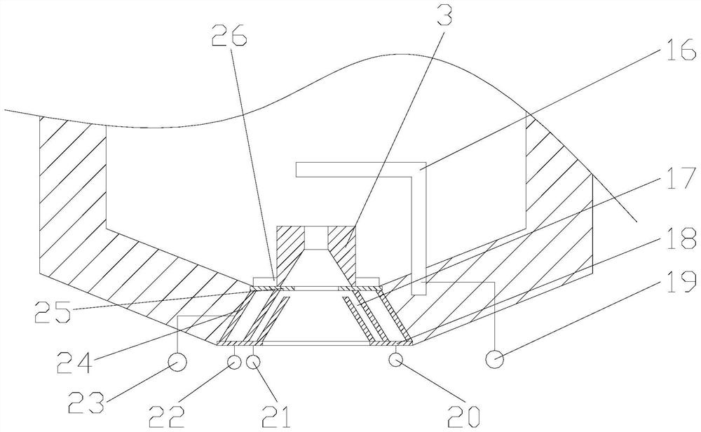
[0037] according to image 3 As shown, the difference with Embodiment 1 and Embodiment 2 is that the outlet pipe 3 is arranged in the inside of the furnace 1, and the bottom of the outlet pipe 3 is provided with a top plate 25, a bottom plate 18, an outlet pipe 3, and a negative electrode. The connection terminal 23 is provided with a heat-resistant electrode 16 inside the melting furnace 1, and the heat-resistant electrode 16 is arranged above the outlet pipe 3, and one end of the heat-resistant electrode 16 is installed on the bottom of the melting furnace 1, and the heat-resistant electrode 16 The positive terminal 19 is installed on the top plate 25, and a nut 26 is fixed on the top plate 25. Threads are provided on the outside of the outlet pipe 3, and are matched with the nut 26. The outlet pipe 3 is connected with the negative terminal 23. The top plate 25 is fixed on the inner side of the bottom of the melting furnace 1, the bottom plate 18 is fixed on the outside of t...
PUM
| Property | Measurement | Unit |
|---|---|---|
| power | aaaaa | aaaaa |
Abstract
Description
Claims
Application Information
 - R&D
- Intellectual Property
- Life Sciences
- Materials
- Tech Scout
- Unparalleled Data Quality
- Higher Quality Content
- 60% Fewer Hallucinations
Browse by: Latest US Patents, China's latest patents, Technical Efficacy Thesaurus, Application Domain, Technology Topic, Popular Technical Reports.
© 2025 PatSnap. All rights reserved.Legal|Privacy policy|Modern Slavery Act Transparency Statement|Sitemap|About US| Contact US: help@patsnap.com


