Controllable light beam diverter based on phase-change material

A technology of phase change material and diverter, applied in instruments, optics, nonlinear optics, etc., can solve the problems of aluminum melting, device polarization sensitivity, and large phase change material layer area.

Inactive Publication Date: 2020-09-22
SHANGHAI JIAO TONG UNIV
View PDF5 Cites 6 Cited by
  • Summary
  • Abstract
  • Description
  • Claims
  • Application Information

AI Technical Summary

Problems solved by technology

However, the phase-change material layer of the device has a large area, and it is difficult to achieve a large-area uniform phase change by laser irradiation; in addition, the surface uses an aluminum strip antenna, and the device is sensitive to polarization, and due to excessive phase-change material amorphization The temperature may cause the aluminum to melt

Method used


Image

  • Controllable light beam diverter based on phase-change material
  • Controllable light beam diverter based on phase-change material
  • Controllable light beam diverter based on phase-change material

Examples


Embodiment

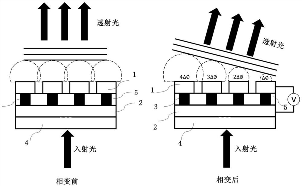
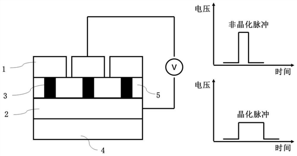
[0021] With silicon dioxide as the substrate, it is mainly composed of three parts: the lower electrodes arranged in parallel in the horizontal direction, the phase change material layer in the cross region, and the upper electrode layer arranged in the vertical direction. The upper and lower electrodes are separated by silicon dioxide. First deposit a layer of ITO on the silicon dioxide substrate, and use electron beam exposure and etching process to form the lower electrode arranged laterally; then deposit the silicon dioxide layer and perform etching to form the phase change material through hole; then deposit the phase change material , to planarize the surface; then deposit a layer of ITO on the surface, and form vertically arranged upper electrodes by electron beam exposure and etching.

[0022] figure 2 It is a schematic diagram of the working principle of the device structure of the present invention. The light beam is incident from below the silicon dioxide substrat...


PUM


Abstract

The invention discloses a controllable light beam diverter based on a phase-change material. The controllable light beam diverter comprises a transversely arranged lower electrode and a longitudinallyarranged upper electrode, wherein a phase change material layer is arranged in the crossed area of the upper electrode and the lower electrode, and a sandwich structure is formed up and down. The light beam enters from the bottom surface, passes through the device and then is output from the surface, and the deflection angle of the output transmission light beam is controlled by controlling the state of the phase-change material. Electric pulses are applied to a phase-change unit by utilizing the upper electrode and the lower electrode of the phase-change material, the electric pulses generate joule heat through the phase-change material to enable the temperature of a phase-change area to rise, and conversion of the phase-change material in a crystalline state or an amorphous state or a mixed state is achieved, so that the output phase of transmission light is changed, and the light beam steering function is achieved. The two-dimensional phase-change array can be flexibly programmed to obtain any output phase distribution, so that the deflection angle of the light beam can be flexibly adjusted. The phase-change material only consumes energy during state switching, so that the device has no static power consumption.

Description

technical field [0001] The invention is a controllable light beam steering device based on phase-change materials, which belongs to the field of integrated optoelectronics. Background technique [0002] With the development of integrated optoelectronic technology, various optoelectronic devices have been extensively studied. Among them, an important technology is the ability to effectively manipulate light beams. Especially in the fields of space optical communication, holographic image generation, and lidar technology, there is an urgent need for miniaturized, high-resolution beam steering technology. For the field of integrated optoelectronics, there are many challenges in realizing the dynamic control of the characteristic parameters of light at the micro-nano scale. [0003] Traditional beam steering structures are mainly divided into two categories: mechanical and non-mechanical. The beam steering structure based on MEMS technology is a typical representative of the m...

Claims


Application Information

Patent Timeline
Patent Type & Authority Applications(China)
IPC IPC(8): G02F1/01G02F1/29
CPCG02F1/0102G02F1/0121G02F1/29
Inventor 周林杰杨星许维翰陆梁军陈建平
Owner SHANGHAI JIAO TONG UNIV
Why Eureka
Try Eureka