
Overcurrent protection element

A technology for protecting components and overcurrents, applied in electrical components, current-responsive resistors, circuits, etc., can solve the problems of weakening structural strength, bending deformation or damage, insufficient area of ​​upper and lower metal layers, etc. Effect

Active Publication Date: 2020-09-22
POLYTRONICS TECH
View PDF4 Cites 2 Cited by
  • Summary
  • Abstract
  • Description
  • Claims
  • Application Information

AI Technical Summary

Problems solved by technology

[0004] The traditional PTC SMD structure usually uses etched metal layers (such as copper layers) to isolate the left and right electrodes. Under the design of large-scale components, the overall area of ​​the upper and lower metal layers still has sufficient structural strength, but as the size of the components becomes smaller , this kind of etching isolation design will make the overall area of ​​the upper and lower metal layers relatively insufficient, resulting in weakened structural strength, so it is easy to cause bending deformation or damage due to the expansion of the PTC material during reflow heating, and this deformation will affect the withstand voltage of the component and the stability of resistance characteristics

Method used


Image

  • Overcurrent protection element
  • Overcurrent protection element
  • Overcurrent protection element

Examples


Embodiment Construction

[0061] In order to make the above and other technical contents, features and advantages of the present invention more comprehensible, relevant embodiments are specifically cited below and described in detail with accompanying drawings.

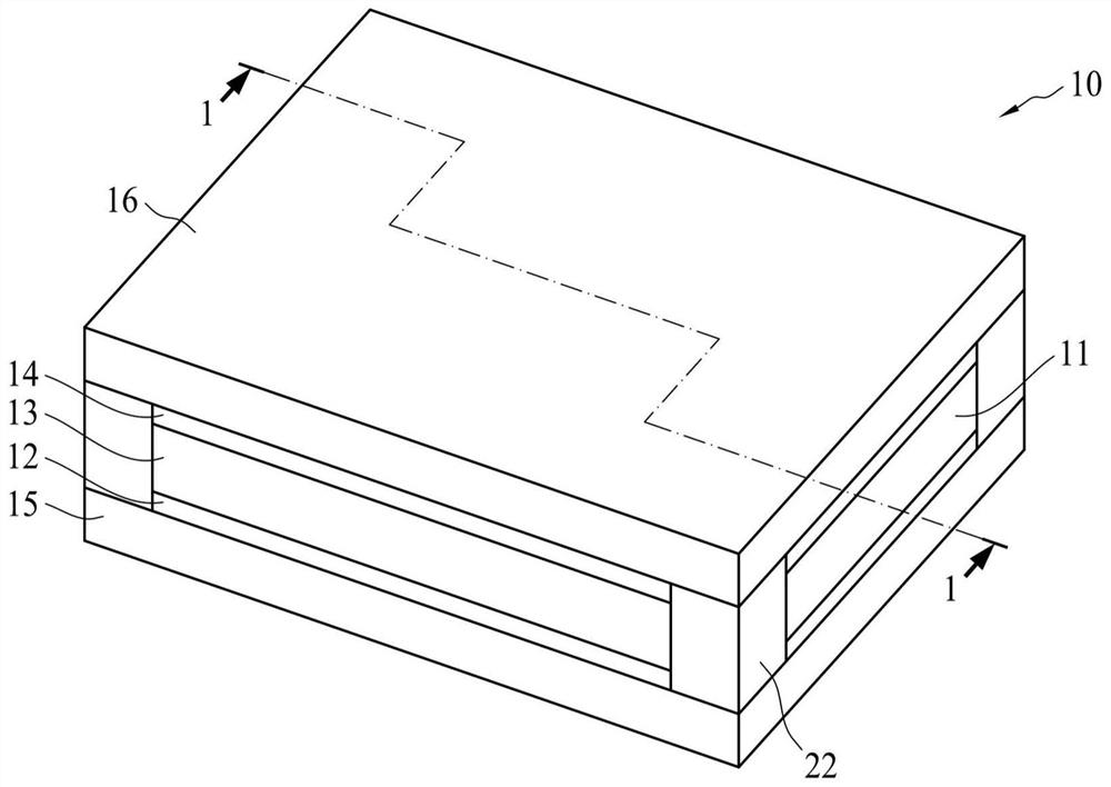
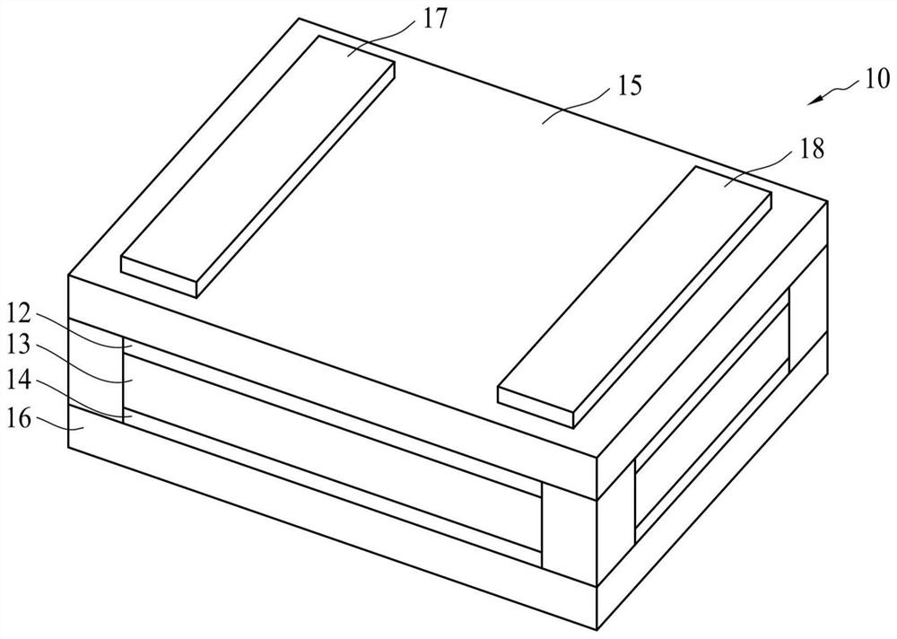
[0062] figure 1 A three-dimensional schematic view showing an overcurrent protection element according to an embodiment of the present invention, figure 2 is to figure 1 The schematic diagram of the overcurrent protection element in flipped upside down. In terms of appearance, the overcurrent protection device 10 has a hexahedral structure including upper and lower surfaces and four side surfaces. The overcurrent protection element 10 includes a PTC element 11 , a first insulating layer 15 , a second insulating layer 16 , a first electrode layer 17 and a second electrode layer 18 . The PTC element 11 is a laminated structure comprising a first conductive layer 12, a second conductive layer 14 and a PTC material layer 13, the first conductive...


PUM


Abstract

An overcurrent protection element has a hexahedral structure including upper and lower surfaces and four side surfaces. The overcurrent protection element comprises a PTC element, a first insulating layer, a first electrode layer and a second electrode layer. The PTC element comprises a first conductive layer, a second conductive layer and a PTC material layer. The first conducting layer is arranged on the first surface of the PTC material layer, the second conducting layer is arranged on the second surface of the PTC material layer, and the second surface is located on the opposite side of the first surface. The first conductive layer is separated into a first conductive block and a second conductive block by at least one interval. The first insulating layer is arranged on the surface ofthe first conductive layer. The first electrode layer is arranged on the surface of the first insulating layer and is electrically connected with the first conductive block. The second electrode layeris arranged on the surface of the first insulating layer and is electrically connected with the second conductive block. The gap includes a major portion that is not parallel to a longitudinal direction of the first electrode layer and the second electrode layer.

Description

technical field [0001] The invention relates to a thermistor, in particular to an overcurrent protection element. Background technique [0002] A positive temperature coefficient (Positive Temperature Coefficient; PTC) can be used to protect a circuit from damage due to overheating or excessive current flow. A positive temperature coefficient device usually includes two electrodes and a resistive material between the two electrodes. This resistance material has a positive temperature coefficient characteristic, that is, it has a low resistance value at room temperature, and when the temperature rises to a critical temperature or an excessive current is generated in the circuit, its resistance value can immediately jump hundreds or thousands of times or more , so as to inhibit the passage of excessive current to achieve the purpose of circuit protection; or applied to the over-temperature detection circuit, which can detect the ambient temperature in advance to instruct the ...

Claims


Application Information

Patent Timeline
IPC IPC(8): H01C7/02H01C7/00H01C7/13H01C1/02H01C1/14H01C1/16
CPCH01C1/02H01C1/14H01C1/16H01C7/001H01C7/027H01C7/13
Inventor 曾郡腾王绍裘
Owner POLYTRONICS TECH
Learn More