

Driving circuit applied to insulated gate bipolar transistor (IGBT)
A technology of bipolar transistors and drive circuits, applied in electrical components, electronic switches, pulse technology, etc., can solve the problems of IGBT turn-on influence, large turn-on loss, and long IGBT turn-on time, so as to achieve optimal control and reduce turn-on time and switching loss effect
- Summary
- Abstract
- Description
- Claims
- Application Information
AI Technical Summary
Problems solved by technology
Method used
Image

Examples
Embodiment approach
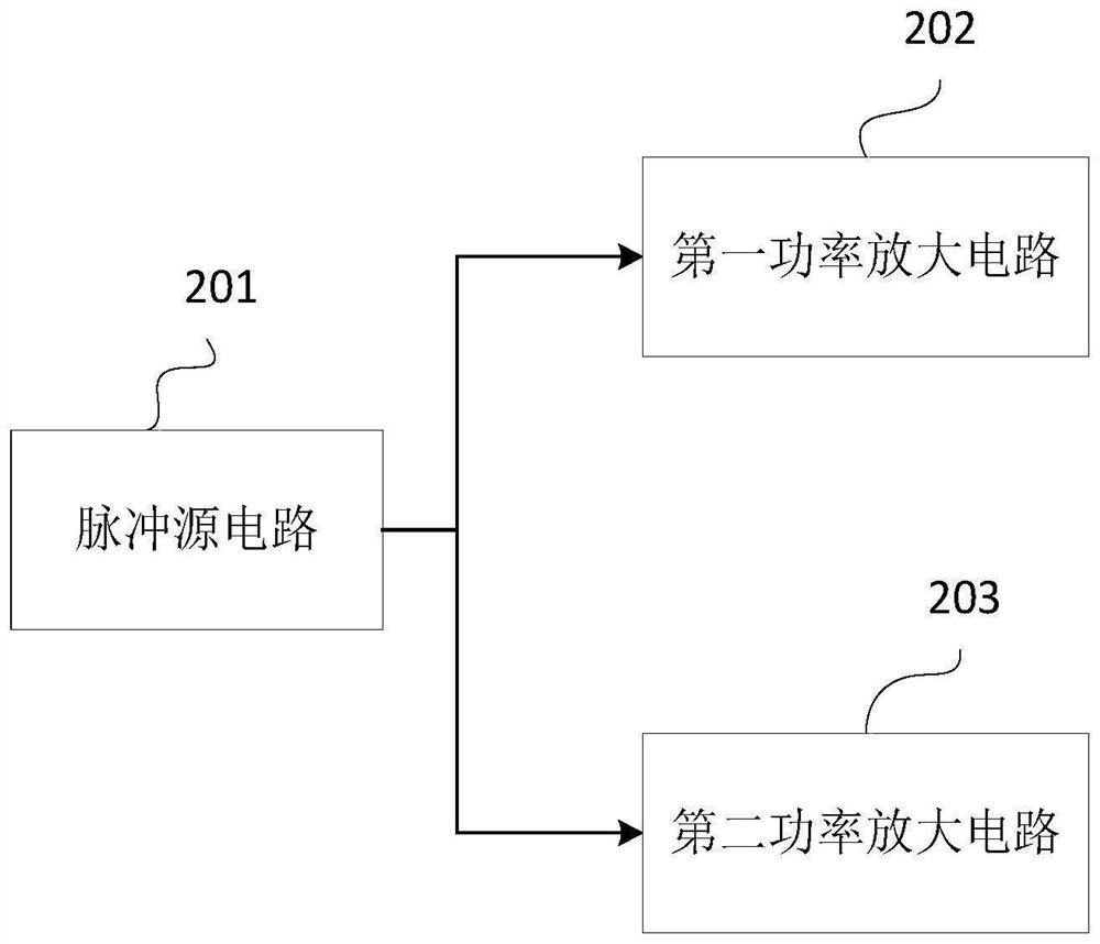
[0094] As an optional implementation manner, the drive circuit further includes:
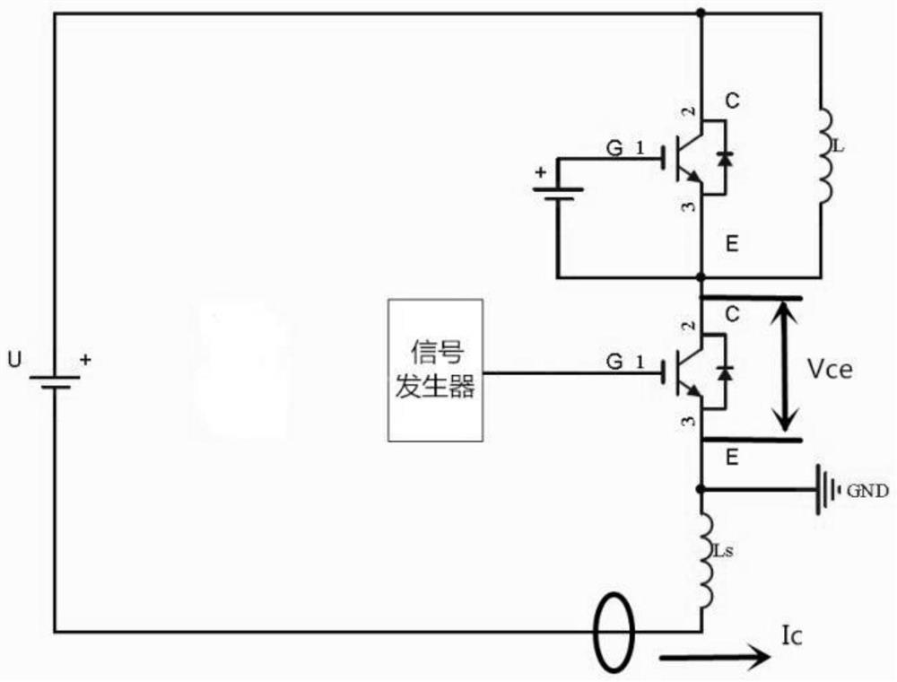
[0095] Equivalent inductance detection circuit, connected to the emitter and collector of the IGBT, used to detect the equivalent stray inductance L of the conductor in the IGBT S .
[0096] Because the emitter stray inductance Ls connected in series with the parasitic inductance is relatively easy to measure (Ls can be measured by a double pulse test), therefore, as long as the measured voltage drop on the stray inductance is close to 0 (or the voltage drop is small), the It can be known that the IGBT in the opening process is in the i C The current rising stage is still i C Invariant stage. According to the different stages in the IGBT turn-on process, the charging and discharging speed of the parasitic capacitance inside the IGBT is controlled to realize soft turn-on of the IGBT and shorten the turn-on time of the IGBT.
[0097] Firstly, the stray inductance Ls needs to be measured by the...
PUM
 Abstract
Description
Claims
Application Information